
But first, a disclaimer. I’m relatively new to NSX-T and playing catch up in a big way. I’m writing this post as a kind of ‘thinking out loud’ exercise. I’ve been firmly planted in the NSX-V world for quite a while now but there is just enough different in T to make me feel like I’ve never seen virtual networking before. To sum it up…

With a Cloud Foundation management cluster freshly upgraded to 3.9.1 and underlying VxRail upgraded to 4.7.410, I needed to spin out a couple of workload domains. One each of NSX-V and NSX-T. NSX-V isn’t exactly the road less travelled at this stage, so I’ll skip that and go straight to T. I was curious what exactly you get when the workload domain deployment finishes. First, choosing T instead of V at the build stage gives you a few different options.
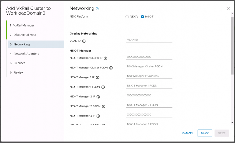
There is nothing too new or demanding here, I entered the VLAN ID that I’m using for the overlay then entered some IP addresses and FQDNs for the various components. Next I selected a couple of unused 10Gbit NICs in the cluster hosts that were specifically installed for NSX-T use. It seems in vSphere 7.0, the requirement for extra physical NICs is going away. Does that mean the setup is going to get more or less complicated?
Some time later I can get back to the question above, “What exactly do you get when Cloud Foundation spins out your NSX-T installation?” The answer, much like it was with NSX-V, is “not much”.
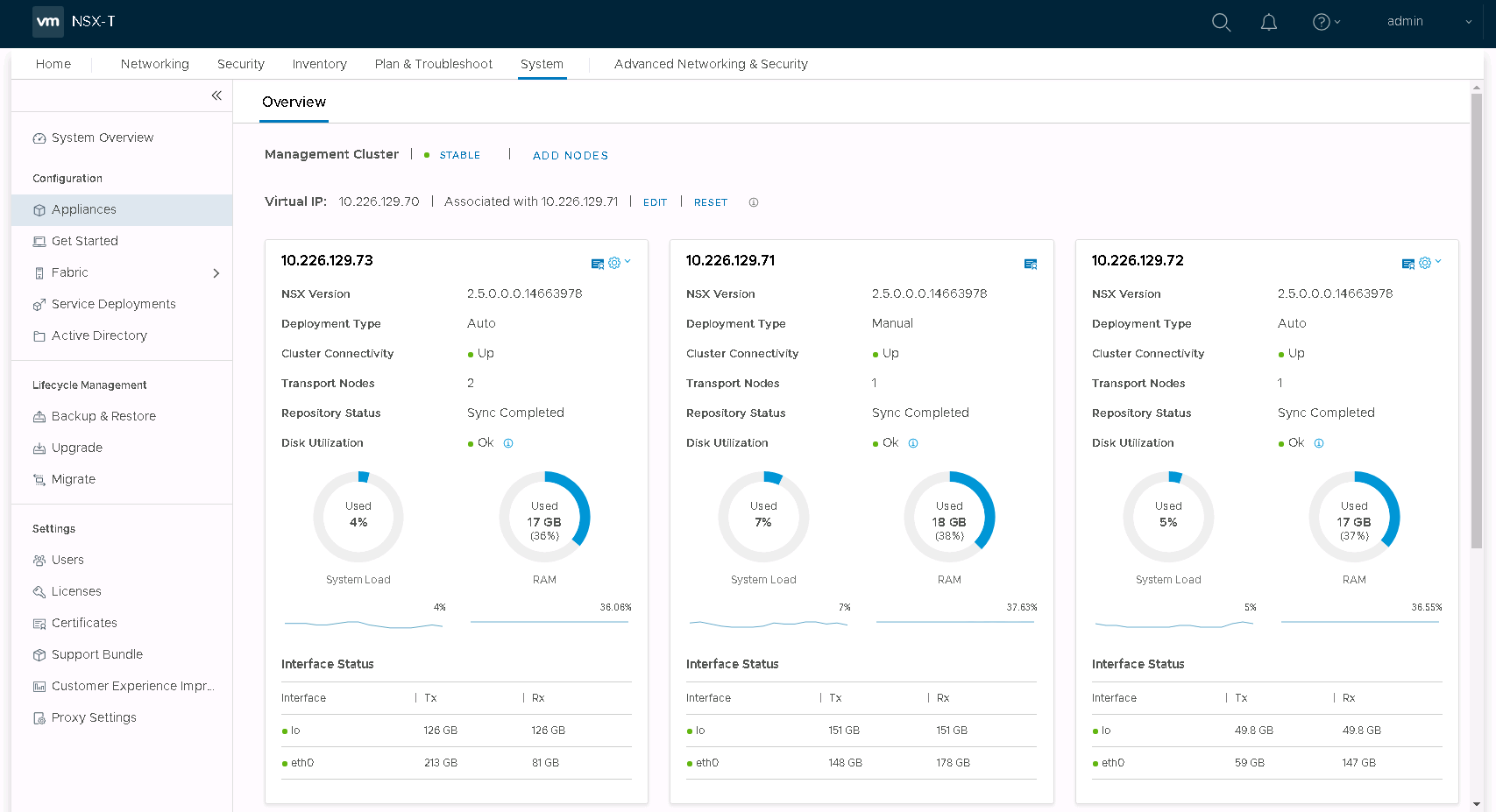
I got a three node manager/controller cluster (deployed on the Cloud Foundation management cluster) with a cluster IP set according to the FQDN and IP address I entered when beginning the setup.
![]()
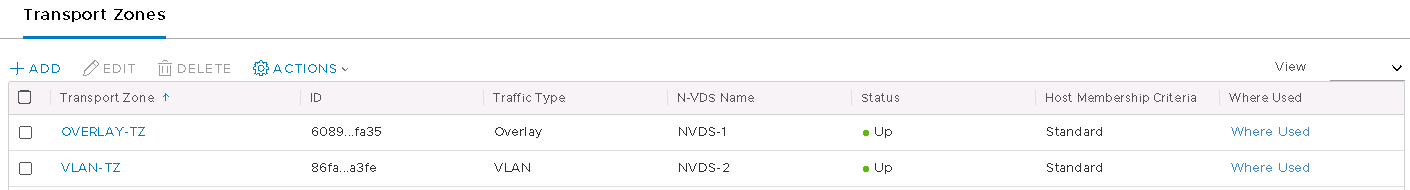
I got the required transport zones, overlay and VLAN. Although somewhat confusing for an NSX-T newbie like me was that they’re both linked to the same N-VDS. Shown above are the original two, plus two I created afterward.
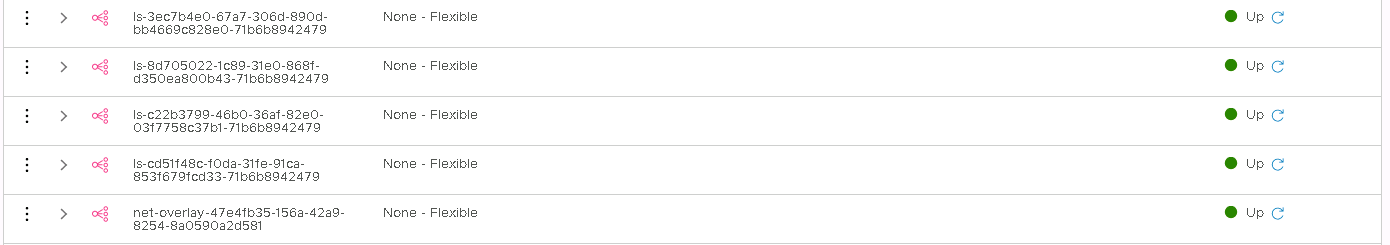
The installation also creates several logical segments. I’m not entirely sure what those are supposed to be for just yet. So as you might expect, I ignored them completely.
Rather annoyingly, Cloud Foundation insists on using DHCP for tunnel endpoint IP addressing in both V and T. Annoying only possibly because I don’t have a readily available DHCP server in the lab. A quick pfSense installation on the management cluster took care of that. It’s a workaround that I fully intend on making permanent one of these days by properly plumbing in a permanent DHCP server. One of these days…
Finally, as far as I’ve seen anyway, the installer prepares the vSphere cluster for NSX-T. That process looks quite similar to how it worked in V.
I set about attacking the ‘out of the box’ configuration with the enthusiasm of a far too confident man and quickly got myself into a mess. I’m hoping to avoid writing too much about what I did wrong, because that’ll end up being very confusing when I start writing about how I fixed it. Long story short, I fixed it by almost entirely ignoring the default installation Cloud Foundation gives you. I walked much of that back to a point where I was happy with how it looked and then built on top of that.
First, Transport Zones. At least two are required. One for overlay (GENEVE) traffic and one or more for VLAN traffic. I created two new transport zones, each with a unique N-VDS.
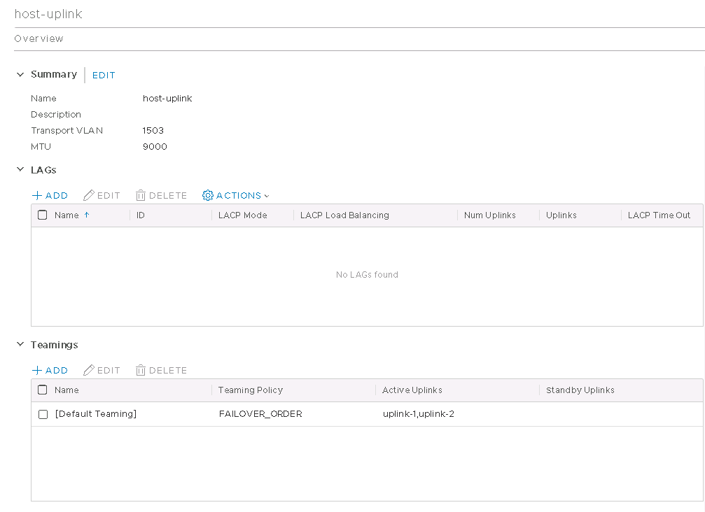
I then created a new uplink profile, pretty much copying the existing one. The transport VLAN (GENEVE VLAN) is tagged in the profile and I’ve set the MTU to 9000. I’ve set the MTU to 9000 everywhere. MTU mismatches are not a fun thing to troubleshoot once the configuration is completed and something doesn’t work properly.
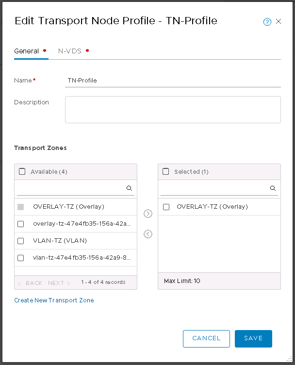
I then created a transport node profile, including only the overlay transport zone.
In that same dialog, I added the overlay N-VDS, set the required profiles (including the uplink profile I created just a moment ago) and mapped the physical NICs to uplinks. I also kept DHCP for the overlay IP addressing. I may revisit this and just move everything over to IP pools as I already had to set up an IP pool for the edge transport node (a bit further down this post).
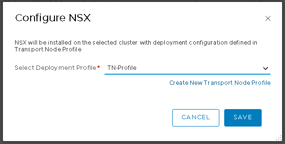
With that done, I reconfigured the vSphere cluster to use my new transport node profile.
That took a few moments for the cluster to reorganise itself.
Next, edge deployment. I set the name and the FQDN, then a couple of passwords. I’m deploying it on the only place I can, in the NSX-T workload domain vCenter and on the vSAN. That’s another thing the default install does; It registers the workload domain vCenter with the NSX-T manager cluster as a compute manager. A bit like logging into NSX-V manager and setting up the link to vCenter & the lookup service.
I assigned it a management IP (which in NSX-T always seems to require CIDR format, even if it doesn’t explicitly ask for it), gateway IP and the correct port group. Finally, configure the transport zones (shown below)
Exactly as in NSX-V, an edge is a north-south routing mechanism. It’ll need a south facing interface to connect to internal NSX-T networks and a north facing interface to connect to the rest of the world. Except a lot of that comes later on, not during the deployment or subsequent configuration of the edge. Which is not like NSX-V at all. Best I can currently make out, an NSX-T edge is like an empty container, into which you’ll put the actual device that does the routing later on. Confused? I know I was.
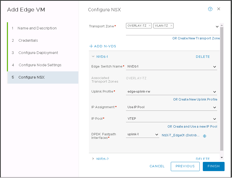
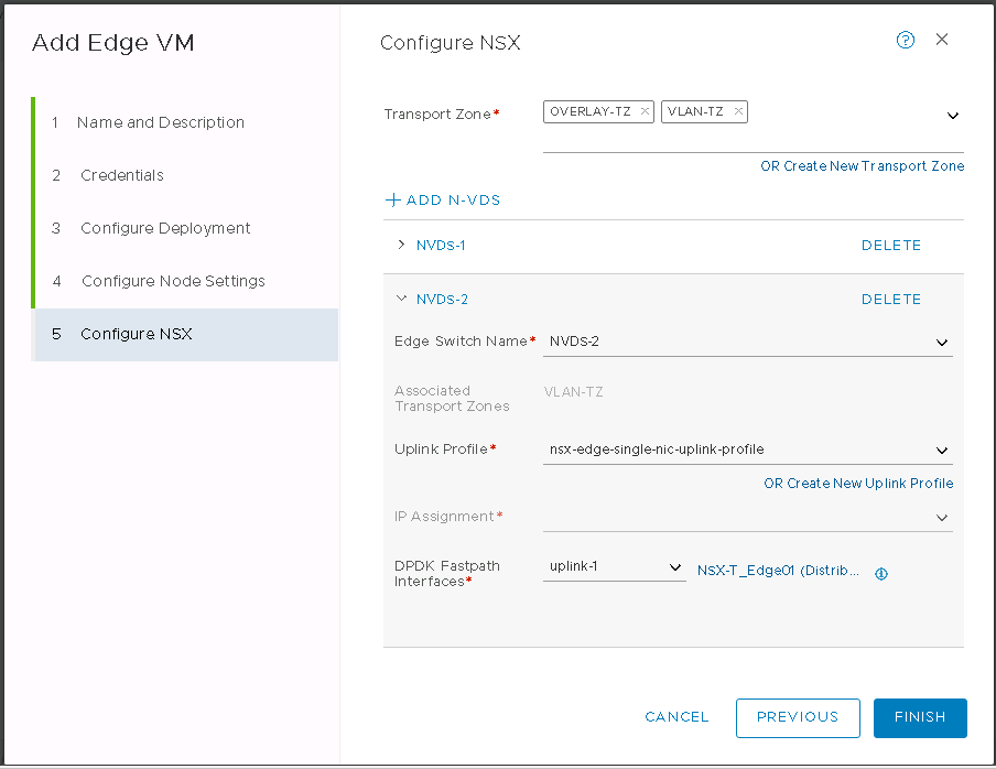
I set both the overlay and VLAN N-VDS on the edge as above. The overlay will get an IP from a pool I created earlier. The VLAN N-VDS doesn’t need an IP address, that happens later when creating a router and an interface on that router.
Finally, the part that caused me a bit of pain. The uplinks. You’ll see above that I now have both N-VDS uplinking to the same distributed port group. This wasn’t always the case. I had initially created two port groups, one for overlay and the other for VLAN traffic. I tagged VLANs on both of them at the vSphere level. This turned out to be my undoing. Overlay traffic was already being tagged by NSX-T in a profile. VLAN traffic is going to be set up to be tagged a bit later. So I was doubling up on the tags. East-West traffic within NSX-T worked fine, I just couldn’t get anything North-South.
The solution of course is to stop tagging in one of the places. So I set the distributed port groups to VLAN trunks and hey presto, everything was happy. After I was done with the entire setup, I felt having two separate port groups was a little confusing and redundant, so I created another one using the same VLAN trunking and migrated everything to that before deleting the original two.
After that, I created an edge cluster and moved my newly deployed edge to it.
Next up, I created a tier-1 gateway. The distributed logical router of the NSX-T world, to make a fairly simplistic comparison to NSX-V.
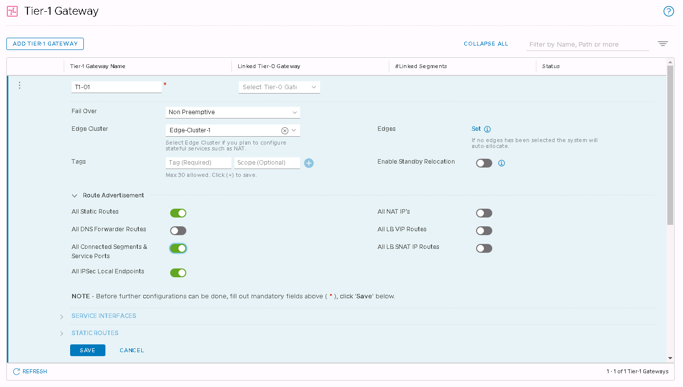
There isn’t much involved in this. Give it a name and an edge cluster to run on. I also enabled route advertisement for static routes and connected segments & service ports. That’ll be required to make sure BGP works when I configure it later on.
Now some segments. Logical switches in the NSX-V world. Except in T, the gateway IP address is set on the segment, not on the logical router.
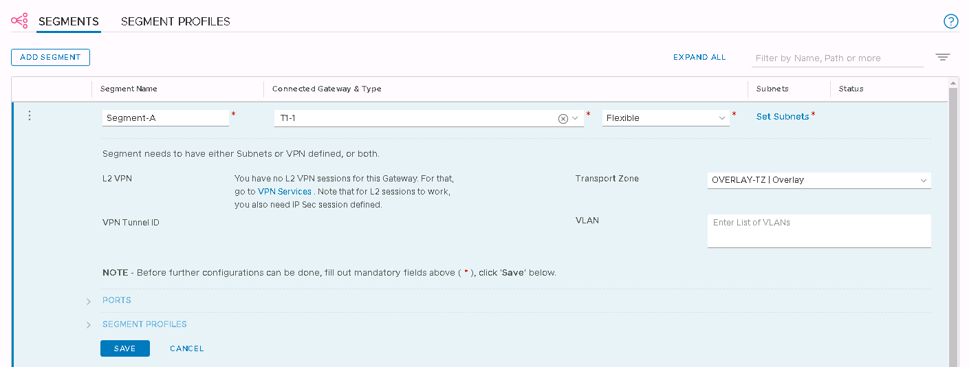
I typed in a segment name and clicked ‘None’ in ‘Connected Gateway & Type’ to select the tier-1 gateway I just created. In the ‘Transport Zone’ drop down, I selected the overlay. All done, saved the segment and ready to move on.
Then onto ‘Set Subnets’ to configure a default gateway for this segment.
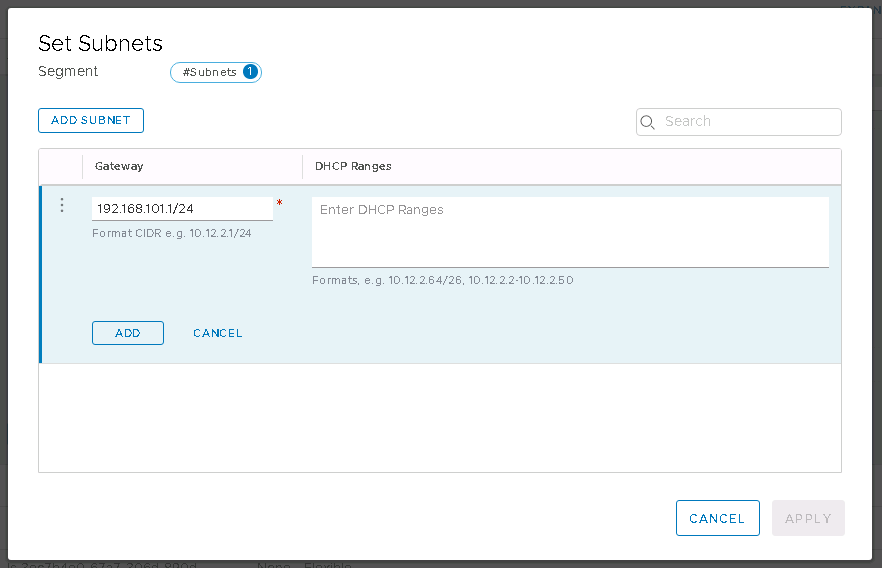
I typed in the gateway IP I wanted to assign to this segment, in CIDR format of course, and clicked Add followed by Apply. Overlay segment done.
Except stop for a moment and do this before moving on. It’ll save some swearing and additional clicking in a few minutes time. Ask me how I know. Along with the overlay segments I created above, I need a VLAN segment to allow my soon to be created tier-0 gateway to get to the outside world.
I created an additional segment called ‘Uplinks’ in my VLAN transport zone and tagged it with the uplink VLAN I’m using on the physical network.
Onto the tier-0 gateway, which will do North-South routing and peer to the top of rack switches using BGP. The initial creation is quite similar to tier-1 creation. I typed in a name, left the default active-active and picked an edge cluster. I need to finish the initial creation of the tier-0 gateway before it’ll allow me to continue, so I clicked save and then yes to the prompt to continue configuring.
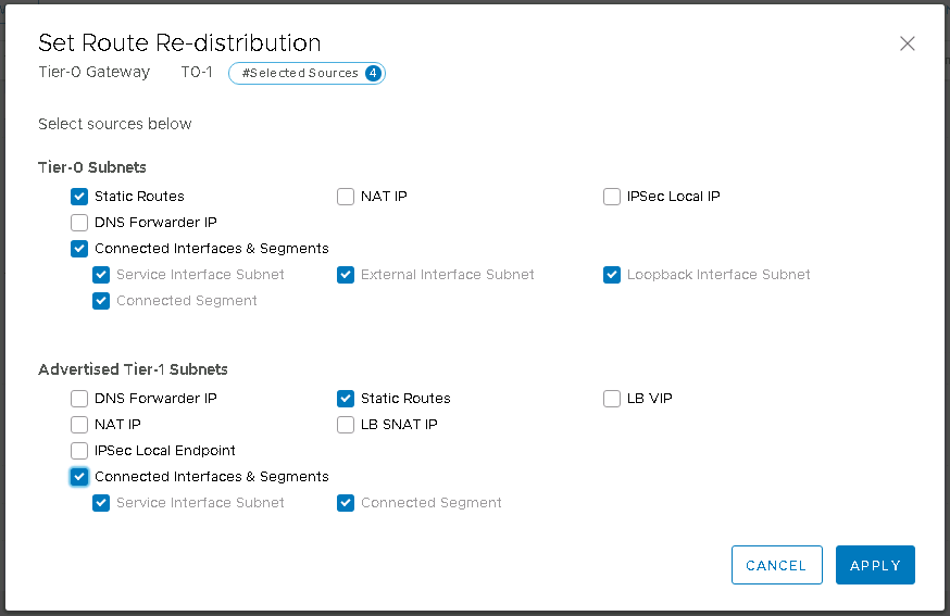
First, route redistribution. This will permit all the segments connected to the tier-1 gateway to be redistributed into the wider network. After clicking set on the route redistribution section, I enabled static routes and connected interfaces & segments for both tier-0 and tier-1.
Another quirk of the NSX-T UI is needing to click save everywhere to save what you’ve just configured. Next section down is interfaces and clicking set on this one opens up the interface addition dialog. I created an interface using the uplink IP address space in the lab, being sure to click ‘add item’ after typing in the IP address in CIDR format. Yet another quirk of the NSX-T UI. I selected my uplinks segment, which I created in the panicked callout above.
I then selected the edge node that this interface should be assigned to. If everything has gone to plan, I can now ping my new interface from the outside world.
Not quite done yet though. Next section is BGP, where I’ll set up the peering with the top of rack switch. The BGP configuration on the ToR is as basic as it gets. Mostly because I want it that way right now. BGP can get as complex as you need it to be.
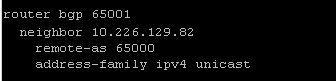
In the BGP section on the tier-0, I left everything at it’s default. There isn’t much of a BGP rollout in the lab already, so the default local AS of 65000 wasn’t going to cause any problems. Under ‘BGP Neighbors’, I clicked set to enter the ToR details. Again, much of this was left at defaults. All I need is the IP address of the interface on my ToR, the remote AS and to set the IP address family to IPv4.

Click save, wait a few seconds and refresh the status. If the peering doesn’t come up, welcome to BGP troubleshooting world. With such a simple config there shouldn’t be many surprises.
But wait, I’m not done yet. Right now I’ve got a BGP peering but there’s no networks being distributed. I haven’t yet connected the tier-1 gateway to the tier-0. This is about the easiest job in NSX-T. I just need to edit the tier-1 gateway, click the drop down for ‘Linked Tier-0 Gateway’ and select the tier-0 gateway. Save that and all the inter-tier peering and routing is done for me in the background.
Checking the switch, I see everything is good. Ignore the other two idle peers, they’ve got nothing to do with this setup.
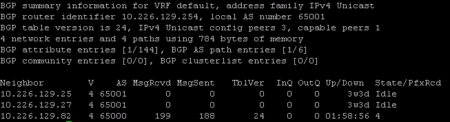
Looks like the switch has received 4 prefixes from the tier-0 gateway. That means that the route redistribution I configured earlier is also working as expected and the tier-1 gateway is successfully linked to the tier-0 gateway.
Yeah, that’s just a little bit more involved than NSX-V. I feel like I need to nuke the lab and rebuild it again just to be sure I haven’t left anything out of this post.