VMware Cloud on AWS; SDDC Groups & Advanced Connectivity

Now that we’ve got our first SDDC up and running with a VPN connection back to our office/data center, it’s time to tear it all down again and turn it into something a little more useful. I need to define the word useful before I go on, because this isn’t going to be a topology that everyone wants or needs. It’s simply a demo of what you can do with SDDC and AWS at scale. If you have multiple SDDCs in a region or across multiple regions and need them to communicate with multiple AWS accounts (possibly managed by AWS Control Tower), then this will be relevant for you. Or if like me you’re a networking nerd and just want to see something cool, read on.

This can obviously also work on a smaller scale, but as some of the components I’ll be deploying will lead to increased AWS charges, there’s likely to be a cheaper way to accomplish your goals if you have a smaller environment.

For reference as we move through this exercise, the below diagram is roughly the end state I want for my environment.

On the left side of the diagram is where our VMware Cloud components live. Right now we’ve just got a single SDDC so I’ll be creating a SDDC group and adding our SDDC to it. The functionality of an SDDC group goes well beyond what we’ll be doing here. It can connect multiple SDDCs together via high bandwidth, low latency links (what VMware calls “Transit Connect”) across up to three AWS regions. SDDC groups can only be formed with SDDCs that are within the same VMC organisation. If your intention isn’t to peer with an AWS account, you can also connect an AWS Direct Connect link to an SDDC group.

Getting back to our scenario, on the right side of the diagram is our existing AWS infrastructure. We’ve got AWS Control Tower setup and to keep things neat and tidy I’ve got a ‘Network Shared Services’ account where all the network interconnects terminate and where our transit gateway is setup. I’ve also got a couple of other accounts running various workloads. Some production, test & dev, sandbox, stuff like that. In some cases we’ve got VPCs created in our network account shared to those accounts and other accounts are free to create their own VPCs and request to attach them to the transit gateway in the networking account.

The bottom of the diagram is the easiest part. I’ve got a VMware cluster on-premises which is currently attached to the AWS transit gateway using a route based VPN connection. If I was in need of more bandwidth or lower latency than a VPN could provide, I’d look at a direct connect (or multiple direct connects for redundancy).

With all that covered, lets launch into the demo.

We start off pretty basic by creating the SDDC group, then things get a little more complicated. To establish the peering between the VMware managed TGW and our TGW, I needed to provide the account number where the TGW is located and the ID of the TGW itself. I then needed to accept the peering request manually. I haven’t enabled auto-accept on the TGW and unless you’d happily give a set of your house keys to everyone that has access to your AWS organisation, you shouldn’t either. The potential for chaos on a grand scale is just too much of a risk to accept.

With that done, I decided to create a prefix list with VMC. That will make routing updates a little easier. A prefix list creates an aggregated list of all network routes from the VMC compute gateway and shares it with the AWS account you specify. So instead of manually adding/removing a route every time you add a new or remove an old segment on VMC, the prefix list will take care of it and ensure our transit gateway has an up to date routing table. Better still, because we’re running BGP over the VPN the routing updates will also be pushed down to the on-premises router without us having to do anything.

To finish up the VMC prefix list setup, I need to accept the resource share from VMC. I then need to create a reference in the transit gateway routing table for it. That’s it. Almost no effort to have dynamic routing everywhere.

After creating the necessary firewall rules within the SDDC, I have full connectivity to my AWS accounts and my SDDCs from on-premises via a single VPN connection. I also have bi-directional connectivity from all of my AWS accounts to my SDDC. A new segment created in the VMC console is immediately pushed to the SDDC vCenter and almost immediately pushed to the AWS and on-premises routing tables. Temper your expectations, it is BGP after all.

The networking is now complete and like all good projects, my introductory journey into VMware Cloud on AWS is experiencing some scope creep. So stay tuned for part three of my two part series, in which I’ll cover the full setup of VMware HCX from my on-premises cluster to my VMC SDDC and migrate some VMs to the cloud.

VMware Cloud on AWS; Getting up and running

I make no bones about being a reformed server hugger. One of my more recent catchphrases is “I’d be a happy man if I never had to build another physical server spec”. So for those currently in the VMware ecosystem, I’ve been turning a lot of attention toward VMware Cloud on various hyperscalers. There is a particular emphasis on AWS and Azure here. GCP is also available, I just don’t get asked about it a lot. Sorry Google.

Some of the most frequent questions I hear include topics such as difficulty to setup and maintain the platform, required knowledge of the underlying hyperscaler, the ubiquitous horror of “vendor lock-in”, and of course the overall cost of the solution. The latter is a whole series of articles in itself, so I’ll be tactically dodging that one here. The short answer, as it so often is, is “it depends”.

Another frequently asked question surrounds the whole idea of “why should I be in the cloud”. There are quite a few well documented use cases for VMware Cloud. The usual ones like disaster recovery, virtual desktop, datacenter extension or even full on cloud migration. One that’s sometimes overlooked is that because SDDCs are so quick to spin up and can be done so with on-demand pricing, they’re great for short lived test environments. Usually, you can create an SDDC, get connectivity to it and be in a position to migrate VMs from your on-premises cluster or DR solution within a couple of hours. No servers to rack, no software to install, no network ports to configure, no week long change control process to trundle through.

For those organisations currently using native cloud services, there are a whole load of additional use cases. Interaction with cloud native services, big data, AI/ML, containers, and many many more buzzwords.

What I can do is show you how quickly you can get a VMC on AWS SDDC spun up and ready for use. The process is largely the same for Azure VMware Solution, with the notable difference that the majority of the VMC interaction in Azure is done via the Azure console itself. The video below gives you an idea of what to expect when you get access to the VMC console and what creating a new SDDC on AWS looks like.

I’ve included some detail on setting up a route based VPN tunnel back to an on-premises device. Policy based and layer 2 VPN are also available, but as my device (a Ubiquiti Edgerouter) is BGP capable I’m taking what I consider to be the easy option. I prefer to use a route based VPN because it makes adding new networks easier and allows a great deal of control using all the usual BGP goodness any network team will be comfortable with. There is also some content covered for firewall rules, because as you might expect they are a core component of controlling access to your newly created SDDC.

Something you may immediately notice (although not explicitly demonstrated in the video) is that the only interaction I had with AWS native services throughout the SDDC creation was to link an existing AWS account to the SDDC. For those without AWS knowledge, this is an incredibly straightforward process with every step walked through in just enough detail. If you’re creating an SDDC, you need to link it to an AWS account. If you don’t already have an AWS account, it’ll take less than five minutes to create one.

The only other requirement right now is to know a little bit about your network topology. Depending on how complex you want to get with VMC on AWS in the future, you’ll need to know what your current AWS and/or on-premises networks look like so you can define a strategy for IP addressing. But of course even if you never plan on connecting the SDDC to anything, you should still have an IP addressing strategy so it doesn’t all go horribly wrong in the future when you need to connect two things you had no plan to connect when you built them.

The one exception I’ll call out for the above is self-contained test environments. What I’m thinking here is a small SDDC hosting some VMs to be tested and potentially linked to an AWS VPC which hosts testing tools, jumpboxes, etc on EC2. If this never touches the production network, fill your boots with all the overlapping IP addresses you could possibly ever need. In this case, creating an environment as close as possible to production is critical to get accurate test results. Naturally, there’s also a pretty decent argument to be made here for lifecycling these type of environments with your infrastructure as code tool of choice.

On that subject, how do you connect a newly created SDDC to an AWS VPC?

This is the process at it’s most basic. Connecting a single VMC SDDC to a single AWS VPC in a linked AWS account. Great for the scenario above where you have self-contained test environments. Not so good if you have multiple production SDDCs in one or more AWS region and several AWS accounts you want them to talk to. For that, we’ve got SDDC groups and transit gateways. That’s where the networking gets a little fancier and we’ll cover that in the next post.

I hope by now I’ve shown that a VMC on AWS SDDC is relatively easy to create and with a bit of help from your network team or ISP, very easy to connect to and start actively using. I’ve tried to keep connectivity pretty basic so far with VPN. If you are already in the AWS ecosystem and are using one or more direct connect links, VMC ties in nicely with that too.

The concept of vendor lock-in comes up more than once here. It’s also something that’s come up repeatedly since Broadcom appeared on the VMware scene. To what extent do you consider yourself locked-in to using VMware and more importantly, what are the alternatives and would you feel any less locked-in to those if you had to do a full lift & shift to a new platform? If you went through the long and expensive process to go cloud native, would going multi-cloud solve your lock-in anxiety? Are all these questions making you break out in a cold sweat?

If you take nothing else away from all the above, I hope you’ve seen that despite some minor hyperscaler platform differences, VMware Cloud is the same VMware platform you’re using on-premises so there is no cloud learning curve for your VMware administrators. You can connect it to your on-premises clusters and use it seamlessly as an extension of your existing infrastructure. You can spin it up on demand and scale up and down hosts quickly if you need disaster recovery. You can test sensitive production apps and environments in isolation.

As I brought up those ‘minor hyperscaler differences’, how would they impact your choice to go with VMC on AWS, Azure VMware Solution, GCP, or another provider? As the VMware product is largely the same on any of the above, it comes down to what relationship you currently have (if any) with the cloud provider. The various providers will have different VMC server specs and connectivity options which would need to be properly accounted for depending on what your use case is for VMC. This is another instance of it being a whole topic by itself. If you’re curious, the comment box is below for your questions.

In the next post on this subject I’ll go into more detail about some complex networking and bring in the concept of SDDC groups, transit connect and AWS transit gateways. I’ll also cover a full end-to-end HCX demo in the next post, so you’ll have what is possibly the best way (in my biased opinion anyway) of getting your VMs into VMware Cloud on AWS.

Deploying Cloud Foundation 3.9.1 on VxRail; Part 6

Last and possibly least (as far as effort required) for the Cloud Foundation stack is to deploy vRealize Operations. Much like the Lifecycle Manager installation, this is relatively painless.

Similar to previous deployments, I’ve already reserved an IP address for all vROPs nodes I intend on deploying and created DNS records. I’ve also entered a license key for the install in SDDC Manager. I’m leaving the install (number and size of nodes deployed) at default. Same as last time, Operations will be deployed onto the pre-created Application Virtual Network.

As you’ll see from the video above, all I had to do was select the license key and enter the FQDNs for each component. At the end of the deployment, I connected the existing workload domain.

That’s pretty much it, nothing too exciting or demanding.

As I said at the start of this series, I’m now moving on to working almost exclusively with Cloud Foundation 4.0 on VxRail 7.0. Thanks to the introduction of new features in both versions, I’m hoping to be able to cover off a few more topics that I didn’t get to in 3.9.x on VxRail 4.5 and 4.7. Things like Kubernetes, external storage connectivity, more in-depth NSX-T configuration and hopefully some PowerOne integration.

Deploying Cloud Foundation 3.9.1 on VxRail; Parts 4 & 5

The next step is a relatively easy one. I’m going to deploy vRealize Lifecycle Manager so that in the steps that follow this, I can use it to deploy both vRealize Automation and vRealize Operations Manager.

As I’ve said above, vRealize Lifecycle Manager is a simple install. One of the prerequisites of course is to have the LCM installer on the system, something I’ve already done. I may have mentioned in previous parts that before I did anything else (right after I completed the SDDC bringup), I downloaded all the packages I knew I was going to need to run through this series. Those packages are; vCenter, NSX-V, vRealize LCM, vRealize Automation and vRealize Operations Manager. I also downloaded any patch or hotfix bundles available.

Another requirement is to have an IP set aside for the LCM VM and a DNS record created. The LCM VM will be deployed onto one of the SDDC application virtual networks which I covered in a previous part. When those two easy tasks are done, I can kick off the LCM deploy in the vRealize Suite menu in the SDDC interface. Side note, if at this stage I tried to deploy anything else (vRA, vROPS), I’d get a helpful error that I need to deploy LCM first.

Less talk, more video…

The deployment process is not a very involved one. Enter an FQDN for the LCM VM, a password for the system admin and root account and that’s pretty much it. Once the deployment is done, I can log into the LCM dashboard and see that the SDDC deployed vRealize Log Insight instance has already been imported into the LCM.

Having the full LCM functionality available is useful, but throughout the final two deployments I’m not going to be using it. Everything will be done from within the vRealize menu in the SDDC UI.

Which brings me onto part five of the series, vRealize Automation. I couldn’t very well just leave this post with a simple LCM install. vRA deployment is a much more detailed and potentially troublesome process. The list of prerequisites is, as you’d expect, quite a bit longer;

  1. IP addresses allocated and DNS records created for all VMs;
      3x vRA appliance VMs
      All Windows IaaS VMs – 2x manager, 2x web, 2x DEM worker and 2x agent.
      Windows SQL VM
  1. Windows VM OVA template built to vRA specifications. Info here on VMware docs.
  2. Multi-SAN certificate signing request generated. Info here on VMware docs.
  3. License key for vRA added to SDDC licenses.
  4. Installation package for vRA downloaded to SDDC.
  5. MS SQL server built and configured with vRA database.

As you’ll see in the video above, the process is quite detailed. Roughly;

  1. Select the appropriate vRA license key.
  2. Enter certificate information. I took the CSR generated above on the SDDC command line and ran it through my Microsoft CA. Generating certs for vRA or vSphere is an entire blog post series in itself.
  3. Upload the Windows OVA for IaaS components.
  4. Validate network subnets for deployment. vRA components will be deployed onto both of the AVNs created at SDDC bringup.
  5. Enter FQDNs for all vRA components.
  6. Enter the active directory user which will be used for the Windows IaaS component VMs.
  7. Enter SQL server and database details. I took the lazy route here and used the SA user. Don’t do that. You should have an appropriately configured active directory user set as owner/admin of the vRA database.
  8. Finally, enter tenant admin details and some details that will be assigned to logins for SSH, Windows local admin, etc.
  9. The last step is to wait a long time for the vRA stack to be deployed. On my four node E460F VxRail cluster, I had to wait a little over three hours. Given the nature of vRA 7.x installation, you don’t see a whole lot of what’s going on behind the scenes (even if you were to manually install vRA). So be patient and wait for that success message.

Once everything was successfully deployed, the existing workload domain was added to the vRA stack. This involves additional agent services being installed and configured on the two IaaS agent VMs. Thankfully, this completes pretty quickly.

Once all that is done in SDDC Manager, I can log in and get to work configuring my vRA instance. But that’s outside the scope of this series, so I haven’t covered it in the video above.

Next up and last up, I’ll be deploying vRealize Operations Manager.

Deploying Cloud Foundation 3.9.1 on VxRail; Part 3

The next task on the list is to add a workload domain to the Cloud Foundation deployment.

The checklist of prerequisites includes the following;

  1. Additional VxRail nodes prepared to version 4.7.410
  2. All DNS records for the new cluster created
  3. IP addresses assigned and DNS records created for NSX flavour of choice
  4. User ‘vxadmin’ created in SSO (I’ll cover this on the video below)

Before starting the process shown in the video, I grabbed three additional VxRail E460F nodes and upgraded RASR to 4.7.410. I kicked off a factory reset and allowed that to run while I’m getting on with the initial creation of the workload domain.

Getting to the content of the video, I first created a new workload domain in SDDC Manager. I entered a workload domain name and all the required details for the new vCenter.

While the vCenter was deploying, I finished up the factory reset on my three new VxRail nodes and made VxRail manager reachable. In my environment, this consists of the following;

  1. Log into two of the three nodes DCUI (KVM via the node’s iDRAC) and enable the shell in the troubleshooting menu.
  2. Set the VLAN ID of two port groups to match the management VLAN. This is done on the shell with the command esxcli network vswitch standard portgroup set -p ” [port group name] ” -v [VLAN ID]. I change VLAN IDs for the port groups ‘Private Management Network’ and ‘Private VM Network’.
  3. Restart loudmouth (the discovery service) on both nodes with the command /etc/init.d/loudmouth restart.
  4. Wait for the primary node to win the election and start the instance of the VxRail Manager VM. You can check which node this is by checking if the VxRail Manager VM is booted. Use the command vim-cmd vmsvc/getallvms to get the ID of the VxRail Manager VM, then use vim-cmd vmsvc/power.getstate [ID] to check if the VM is powered on.
  5. On the primary node, set the ‘VM Network’ port group to the management VLAN (same command as above). Failing to set this will lead to massive confusion as to why you can’t reach the temporary management IP you’ll assign to the host in the next step. You’ll check VLAN’s, trunks, spanning tree and twenty other things before groaning loudly and going back to the node to set the VLAN. Ask me how I know.
  6. In the DCUI, give the primary node a temporary IP address on the management VLAN.
  7. Log into vSphere client on the node and open the VxRail Manager VM console. Log in as root using the default password.
  8. Set a temporary IP on the VxRail Manager VM with the command /opt/vmware/share/vami/vami_set_network eth0 STATICV4 [ip address] [subnet mask] [gateway].
  9. Restart the marvin and loudmouth services on the VxRail manager VM with systemctl restart vmware-marvin and systemctl restart vmware-loudmouth.
  10. Give it a moment for those services to restart, then open the temporary VxRail Manager IP in a browser.
  11. Go back to the third (and any subsequent) node(s) and perform steps 1 to 3 above.

Before kicking off the VxRail build, I go back and remove the temporary management IP address I set on the primary node to prevent any confusion on the built cluster. I’ve found in the past that SDDC sometimes isn’t too happy if there are two management IP addresses on a host. It tends to make the VCF bringup fail at about the NFS datastore mount stage.

Before anyone says anything; Yes, this would be a lot easier if I had DHCP in the environment and just used the VxRail default VLAN for node discovery. But this is a very useful process to know if you find yourself in an environment where there is no DHCP or there are other network complications that require a manual workaround. I may just have to create another short video on this at some stage soon.

With my vCenter ready and my VxRail ready to run, I’ll fire up the wizard and allow the node discovery process to run. After that, I chose to use an existing JSON configuration file I had for another workload domain I created not too long ago. I’ll be changing pretty much everything for this run, it just saves some time to have some of the information prepopulated. I am of course building this VxRail cluster with an external vCenter, the same vCenter that SDDC Manager just created.

The installer kicks off and if I log into the SDDC management vCenter, I can watch the workload domain cluster being built.

A little while later the cluster build is completed, but I’m not done yet. I need to go back into SDDC Manager and complete the workload domain addition. Under my new workload domain, which is currently showing as ‘activating’, I need to add my new VxRail cluster. SDDC Manager discovers the new VxRail Manager instance, I confirm password details for the nodes in the cluster and choose my preferred NSX deployment. In this case, I’m choosing NSX-V. I only have two physical 10Gbit NICs in the nodes, so NSX-T isn’t an option. Roll on Cloud Foundation 4.0 for the fix to that.

I enter all the details required to get NSX-V up and running; NSX manager details, NSX controllers and passwords for everything. I choose licenses to apply for both NSX and vSAN, then let the workload domain addition complete. All done, the configuration state now shows ‘active’ and I’m all done.

Except not quite. In the video I have also enabled vRealize Log Insight on the new workload domain before finishing up.

On the subject of the vRealize Suite, that’s up next.

Deploying Cloud Foundation 3.9.1 on VxRail; Parts 1 & 2

Before I move on and dedicate the majority of my time to Cloud Foundation 4, I created a relatively short series of screencasts detailing the process to deploy Cloud Foundation 3.9.1 on VxRail. 

I say detailing, I really mean quite a high-level overview. It’s by no means a replacement for actually reading and understanding the documentation. I’ve split the whole show into six parts;

  1. Deploying Cloud Builder
  2. Performing the Cloud Foundation bringup
  3. Creating a workload domain
  4. Deploying vRealize Lifecycle Manager
  5. Deploying vRealize Automation
  6. Deploying vRealize Operations Manager

It’s my hope that each of the fairly brief videos will provide an overview of the deployment process and maybe even help someone that is in a “what the hell is this screen and what do I do next?” scenario.

My environment for this series is 7 E460F VxRail nodes. The nodes have had a RASR upgrade to 4.7.410 and four of them have already been built into a cluster for my Cloud Foundation management domain. It goes without saying that I’m following the VMware bill of materials for version 3.9.1.

Before we do anything, we need to get Cloud Builder running. That’s what I’ve done in part 1 below. For all the videos in this series, it’s better to view fullscreen. Unless you like squinting at microscopic text of course.

Prerequisites for this part are easy, you need the Cloud Builder OVA. Unfortunately, the prerequisites aren’t going to remain this easy to satisfy throughout the rest of the series.

In the video above, I’ve also included two of the prerequisites for the next part;

  1. Externalising the vCenter server. This was made much easier in later VxRail builds thankfully.
  2. Converting the management portgroup to ephemeral binding.

Because simply deploying an OVA isn’t exactly face meltingly exciting, I’m including the second part of the series in this post also.

That second part being the actual deployment/bringup of Cloud Foundation and establishing the management cluster.

The prerequisites for this part are slightly more demanding. In what could be a frustrating move, I’m going to insist that you go out and search for these yourself. Or just deploy Cloud Builder and check out the extensive list you get when you attempt a bringup. The three that concern me most are;

  1. Make sure you have end to end jumbo frames configured (MTU of 9000). VMware don’t specifically recommend this on all VLANs, but I usually go jumbo everywhere to save me time and potential troubleshooting headaches later.
  2. Enable and configure BGP on your top of rack switches. In 3.9.1, we’re going with BGP right from the start with something VMware is calling “Application Virtual Networks” (AVNs). Or to everyone else, NSX-V logical switches. Two of these will be configured from day 1, so we’ll need to set up BGP peers on the ToRs and make sure the network is set up to route to the subnets for the AVNs (in the case where you’re not running dynamic routing everywhere). 
  3. DHCP for VXLAN VTEPs. I don’t have DHCP readily available in the lab, so this has been a pain for me since the first VCF on VxRail deployment. I end up deploying pfsense onto the management cluster, configuring it and then shutting it down and removing it from inventory. Once the Cloud Foundation bringup validation is complete and bringup is running, I hop back into vCenter and add the VM to inventory and power it up. That’s shown in the video below. Reason being that if any unknown VMs are running while bringup validation is running, it seems to make it fail. 

Everything else is taken care of. I’ve configured all the DNS records and ensured the cluster nodes are healthy in vCenter.

A word of caution before continuing. Be sure, very sure, that your deployment parameter excel spreadsheet is correctly completed. Make sure all the IP addresses and FQDNs you’ve entered are correct and everything is set up in DNS and forward & reverse lookups are perfect. The bringup validation won’t necessarily catch all errors and if bringup kicks off or gets half way through and then fails due to an incorrect IP address, you’re going to be resetting your VxRail and starting from scratch. Ask me how I know…

Having a look at the Planning & Preparation guide is probably a wise choice before we go kicking off any bringups.

On with part 2 and getting the management domain up and running.

In the above video, you’ll see the bringup failed while validating BGP. When Cloud Builder deploys the NSX edge service gateways for the AVN subnets, it doesn’t specify default gateways. So no traffic can get out of the two AVN NSX segments. Digging through the planning & prep guide, I can’t see any specific requirement for what I’ve done. That being to enable default-originate within the BGP neighbor config for each of the four peerings to the ESGs. That way, a default route is advertised to the ESGs and everybody is happy. Maybe this is environment specific, maybe it’s an omission from the guide. Either way, works for me in my lab!

That’s it for now. Next up, I’ll be adding a workload domain.

Making NSX-T 2.5 work in Cloud Foundation 3.9.1

But first, a disclaimer. I’m relatively new to NSX-T and playing catch up in a big way. I’m writing this post as a kind of ‘thinking out loud’ exercise. I’ve been firmly planted in the NSX-V world for quite a while now but there is just enough different in T to make me feel like I’ve never seen virtual networking before. To sum it up…

With a Cloud Foundation management cluster freshly upgraded to 3.9.1 and underlying VxRail upgraded to 4.7.410, I needed to spin out a couple of workload domains. One each of NSX-V and NSX-T. NSX-V isn’t exactly the road less travelled at this stage, so I’ll skip that and go straight to T. I was curious what exactly you get when the workload domain deployment finishes. First, choosing T instead of V at the build stage gives you a few different options.

There is nothing too new or demanding here, I entered the VLAN ID that I’m using for the overlay then entered some IP addresses and FQDNs for the various components. Next I selected a couple of unused 10Gbit NICs in the cluster hosts that were specifically installed for NSX-T use. It seems in vSphere 7.0, the requirement for extra physical NICs is going away. Does that mean the setup is going to get more or less complicated?

Some time later I can get back to the question above, “What exactly do you get when Cloud Foundation spins out your NSX-T installation?” The answer, much like it was with NSX-V, is “not much”.

I got a three node manager/controller cluster (deployed on the Cloud Foundation management cluster) with a cluster IP set according to the FQDN and IP address I entered when beginning the setup.

I got the required transport zones, overlay and VLAN. Although somewhat confusing for an NSX-T newbie like me was that they’re both linked to the same N-VDS. Shown above are the original two, plus two I created afterward.

The installation also creates several logical segments. I’m not entirely sure what those are supposed to be for just yet. So as you might expect, I ignored them completely.

Rather annoyingly, Cloud Foundation insists on using DHCP for tunnel endpoint IP addressing in both V and T. Annoying only possibly because I don’t have a readily available DHCP server in the lab. A quick pfSense installation on the management cluster took care of that. It’s a workaround that I fully intend on making permanent one of these days by properly plumbing in a permanent DHCP server. One of these days…

Finally, as far as I’ve seen anyway, the installer prepares the vSphere cluster for NSX-T. That process looks quite similar to how it worked in V.

I set about attacking the ‘out of the box’ configuration with the enthusiasm of a far too confident man and quickly got myself into a mess. I’m hoping to avoid writing too much about what I did wrong, because that’ll end up being very confusing when I start writing about how I fixed it. Long story short, I fixed it by almost entirely ignoring the default installation Cloud Foundation gives you. I walked much of that back to a point where I was happy with how it looked and then built on top of that.

First, Transport Zones. At least two are required. One for overlay (GENEVE) traffic and one or more for VLAN traffic. I created two new transport zones, each with a unique N-VDS.

I then created a new uplink profile, pretty much copying the existing one. The transport VLAN (GENEVE VLAN) is tagged in the profile and I’ve set the MTU to 9000. I’ve set the MTU to 9000 everywhere. MTU mismatches are not a fun thing to troubleshoot once the configuration is completed and something doesn’t work properly.

I then created a transport node profile, including only the overlay transport zone.

In that same dialog, I added the overlay N-VDS, set the required profiles (including the uplink profile I created just a moment ago) and mapped the physical NICs to uplinks. I also kept DHCP for the overlay IP addressing. I may revisit this and just move everything over to IP pools as I already had to set up an IP pool for the edge transport node (a bit further down this post).

With that done, I reconfigured the vSphere cluster to use my new transport node profile.

That took a few moments for the cluster to reorganise itself.

Next, edge deployment. I set the name and the FQDN, then a couple of passwords. I’m deploying it on the only place I can, in the NSX-T workload domain vCenter and on the vSAN. That’s another thing the default install does; It registers the workload domain vCenter with the NSX-T manager cluster as a compute manager. A bit like logging into NSX-V manager and setting up the link to vCenter & the lookup service.

I assigned it a management IP (which in NSX-T always seems to require CIDR format, even if it doesn’t explicitly ask for it), gateway IP and the correct port group. Finally, configure the transport zones (shown below)

Exactly as in NSX-V, an edge is a north-south routing mechanism. It’ll need a south facing interface to connect to internal NSX-T networks and a north facing interface to connect to the rest of the world. Except a lot of that comes later on, not during the deployment or subsequent configuration of the edge. Which is not like NSX-V at all. Best I can currently make out, an NSX-T edge is like an empty container, into which you’ll put the actual device that does the routing later on. Confused? I know I was.

I set both the overlay and VLAN N-VDS on the edge as above. The overlay will get an IP from a pool I created earlier. The VLAN N-VDS doesn’t need an IP address, that happens later when creating a router and an interface on that router.

Finally, the part that caused me a bit of pain. The uplinks. You’ll see above that I now have both N-VDS uplinking to the same distributed port group. This wasn’t always the case. I had initially created two port groups, one for overlay and the other for VLAN traffic. I tagged VLANs on both of them at the vSphere level. This turned out to be my undoing. Overlay traffic was already being tagged by NSX-T in a profile. VLAN traffic is going to be set up to be tagged a bit later. So I was doubling up on the tags. East-West traffic within NSX-T worked fine, I just couldn’t get anything North-South.

The solution of course is to stop tagging in one of the places. So I set the distributed port groups to VLAN trunks and hey presto, everything was happy. After I was done with the entire setup, I felt having two separate port groups was a little confusing and redundant, so I created another one using the same VLAN trunking and migrated everything to that before deleting the original two.

After that, I created an edge cluster and moved my newly deployed edge to it.

Next up, I created a tier-1 gateway. The distributed logical router of the NSX-T world, to make a fairly simplistic comparison to NSX-V.

There isn’t much involved in this. Give it a name and an edge cluster to run on. I also enabled route advertisement for static routes and connected segments & service ports. That’ll be required to make sure BGP works when I configure it later on.

Now some segments. Logical switches in the NSX-V world. Except in T, the gateway IP address is set on the segment, not on the logical router.

I typed in a segment name and clicked ‘None’ in ‘Connected Gateway & Type’ to select the tier-1 gateway I just created. In the ‘Transport Zone’ drop down, I selected the overlay. All done, saved the segment and ready to move on.

Then onto ‘Set Subnets’ to configure a default gateway for this segment.

I typed in the gateway IP I wanted to assign to this segment, in CIDR format of course, and clicked Add followed by Apply. Overlay segment done.

Except stop for a moment and do this before moving on. It’ll save some swearing and additional clicking in a few minutes time. Ask me how I know. Along with the overlay segments I created above, I need a VLAN segment to allow my soon to be created tier-0 gateway to get to the outside world. 

I created an additional segment called ‘Uplinks’ in my VLAN transport zone and tagged it with the uplink VLAN I’m using on the physical network.

Onto the tier-0 gateway, which will do North-South routing and peer to the top of rack switches using BGP. The initial creation is quite similar to tier-1 creation. I typed in a name, left the default active-active and picked an edge cluster. I need to finish the initial creation of the tier-0 gateway before it’ll allow me to continue, so I clicked save and then yes to the prompt to continue configuring.

First, route redistribution. This will permit all the segments connected to the tier-1 gateway to be redistributed into the wider network. After clicking set on the route redistribution section, I enabled static routes and connected interfaces & segments for both tier-0 and tier-1.

Another quirk of the NSX-T UI is needing to click save everywhere to save what you’ve just configured. Next section down is interfaces and clicking set on this one opens up the interface addition dialog. I created an interface using the uplink IP address space in the lab, being sure to click ‘add item’ after typing in the IP address in CIDR format. Yet another quirk of the NSX-T UI. I selected my uplinks segment, which I created in the panicked callout above.

I then selected the edge node that this interface should be assigned to. If everything has gone to plan, I can now ping my new interface from the outside world.

Not quite done yet though. Next section is BGP, where I’ll set up the peering with the top of rack switch. The BGP configuration on the ToR is as basic as it gets. Mostly because I want it that way right now. BGP can get as complex as you need it to be.

In the BGP section on the tier-0, I left everything at it’s default. There isn’t much of a BGP rollout in the lab already, so the default local AS of 65000 wasn’t going to cause any problems. Under ‘BGP Neighbors’, I clicked set to enter the ToR details. Again, much of this was left at defaults. All I need is the IP address of the interface on my ToR, the remote AS and to set the IP address family to IPv4.

Click save, wait a few seconds and refresh the status. If the peering doesn’t come up, welcome to BGP troubleshooting world. With such a simple config there shouldn’t be many surprises.

But wait, I’m not done yet. Right now I’ve got a BGP peering but there’s no networks being distributed. I haven’t yet connected the tier-1 gateway to the tier-0. This is about the easiest job in NSX-T. I just need to edit the tier-1 gateway, click the drop down for ‘Linked Tier-0 Gateway’ and select the tier-0 gateway. Save that and all the inter-tier peering and routing is done for me in the background.

Checking the switch, I see everything is good. Ignore the other two idle peers, they’ve got nothing to do with this setup.

Looks like the switch has received 4 prefixes from the tier-0 gateway. That means that the route redistribution I configured earlier is also working as expected and the tier-1 gateway is successfully linked to the tier-0 gateway.

Yeah, that’s just a little bit more involved than NSX-V. I feel like I need to nuke the lab and rebuild it again just to be sure I haven’t left anything out of this post.

VxRack SDDC to VCF on VxRail; Part 4. Expanding Workload Domains

Quick Links
Part 1: Building the VCF on VxRail management cluster
Part 2: Virtual Infrastructure Workload Domain creation
Part 3: Deploy, Configure and Test VMware HCX
Part 4: Expanding Workload Domains

At the end of part 3, I said

With HCX installed and running, I can move onward. Out of the frying pan and into the fire. Getting some of those production VMs moving.

Except we won’t be doing that, because in a lab scenario, it’d be boring. There isn’t really any interdependency between VMs in my lab. There are no multi-tiered apps running, no network micro-segmentation or any one of the other countless gotchas you have to plan around for a production environment. I’d end up writing a long, detailed post about moving some test VMs between VxRack and VxRail clusters. I’d be rehashing a lot of what I wrote in the previous post regarding VMware HCX migration types and varied migration strategies.

So instead, straight onto expanding workload domains.

After using HCX to migrate some of the initial workload to the VCF on VxRail VI workload domain, the three node cluster is naturally going to get a little resource constrained. At the same time, resources are going to be freed up on the VxRack SDDC nodes. So using the process I detailed in part 1 to build the management and VI workload domain clusters, I’ll convert some more VxRack SDDC nodes into VxRail nodes and expand my VI workload domain.

To briefly recap the conversion process;

  1. Decommission the VxRack SDDC node in SDDC manager.
  2. Power the node down and install hardware (if necessary).
  3. Complete all required firmware updates.
  4. Mount VxRail RASR ISO image and factory reset the node.

With the above completed, I’ve got a brand new VxRail node ready to go. Within vCenter, right click on the cluster name and from the VxRail menu, select Add VxRail Hosts. It may take a few seconds for the new node details to populate. Once the node(s) appear in the list, I can continue by clicking the Add button.

In this case, I’m only going to add one of the four discovered nodes to the cluster.

Provide credentials of an administrative user.

Then verify that a sufficient number of IP addresses in the management, vMotion and vSAN IP pools are free. If not, create additional pools.

Provide more credentials

Finally confirm if the new node(s) will remain in maintenance mode once addition is complete.

Everything looks good, click validate. Once the validation process finishes successfully, I can proceed with the node addition.

Within a few minutes, the new node will be added to the cluster in vCenter. The only problem now is that SDDC manager knows nothing about it. So I’ll fix that. A moderate amount of digging through menus is required. Within SDDC manager, select Inventory > Workload Domains. I picked the workload domain I want to add the node to, in this case ‘thor-vi1-cluster’. Click the Clusters tab to display the VxRail clusters within this workload domain. I don’t believe I’ve covered it yet, but yes, a single workload domain can contain one or more VxRail clusters. Click the cluster to which the node will be added. As you can see in the screenshot below, the actions menu contains a link to add the new node.

All going well (and assuming my new node is setup correctly), it’ll appear in the next dialog (below) after a brief period of discovery.

It did, so no loudmouth troubleshooting is required. Incidentally, as all my top of rack multicast configuration has been carried out on a specific VLAN, I need to do a little modification to new nodes so they’ll see and contribute to the multicast group properly. Otherwise, VxRail manager isn’t going to discover anything. This is slightly different in VxRail 4.7 code, which introduces two new portgroups. Long story short, when I’m bringing up a new node, I change the VLAN assignment for “Private Management Network” to my custom VLAN. The CLI commands are basic, but I’ll include them below for the sake of completeness.

“esxcli network vswitch standard portgroup list” – to check the VLAN assignments for the portgroups.

“esxcli network vswitch standard portgroup set -p “Private Management Network” -v [VLAN]” – to set the VLAN on which multicast is running.

In the spirit of not over complicating it, I always use the ESXi management VLAN as my private management network VLAN. But if you wanted to segregate multicast traffic to its own VLAN, the option is there.

Nothing terribly exciting happens after the above dialog I’m afraid. All there is left to do is watch the status pane in SDDC manager as the new node switches from activating to active. After that happens, the new node is ready to go.

The above is an example of converting and adding a single new node into an existing VxRail cluster & SDDC workload domain. It’s not difficult to imagine that if you were to convert nodes one by one on a large VxRack SDDC system, it would be a job for life. When the migration from VxRack to VxRail is in progress, it makes sense to include as many nodes as possible in each iteration of convert & expand. I can convert several concurrently as easily as converting one, with little additional time penalty. When the time comes to add those converted nodes into a VxRail cluster, it can be a bulk operation.

Needless to say, it should be extensively planned, depending on factors in your environment. If I migrate X amount of VM load from VxRack SDDC cluster Y, then in turn I can remove X number of nodes from VxRack SDDC Cluster Y and immediately make that compute & vSAN storage capacity available on VxRail Cluster Y. That, of course, is a gross oversimplification. What I’m really getting at is, if you’ve got the capacity, don’t do it one by one or you’ll go nuts long before you’ve got your several hundred node VxRack SDDC to VCF on VxRail migration completed.

As you might expect, the above is a ‘rinse & repeat’ process until all the production load is migrated successfully from VxRack to VxRail. Either continue to add capacity to existing VxRail clusters/workload domains, or create new additional workload domains using the process covered in part two of this series.

As for the questions I’ve been answering throughout this series;

How long is it going to take? – About four hours to convert a node if you insist on doing it the painful (one by one) way. That is everything from the initial decommission out of VxRack SDDC manager, hardware changes (if required), creating the RASR partition, installing the VxRail code and waiting for the ESXi configuration. Adding nodes to VxRail clusters and VCF workload domains is pretty trivial. Let’s add another 15 minutes or so for that. As above, many nodes at once make lighter work. Lighter still if you automate the process.

How much of it can be automated? – So, so much. Almost the entire conversion process is a candidate for automation. In an ideal scenario, I’d let automation take the reins after I’ve confirmed that the node(s) are successfully decommissioned from VxRack SDDC and I’ve completed any necessary hardware changes. I probably wouldn’t automate the addition of those newly converted nodes to VxRail clusters, but maybe that’s just me.

Next up, I’m going to be doing something short and sweet. I’ll be destroying the VxRack SDDC management workload domain and reclaiming the resources therein.

VxRack SDDC to VCF on VxRail; Part 3. Installing VMware HCX.

Quick Links
Part 1: Building the VCF on VxRail management cluster
Part 2: Virtual Infrastructure Workload Domain creation
Part 3: Deploy, Configure and Test VMware HCX
Part 4: Expanding Workload Domains

I’ve got Cloud Foundation up and running and a VI workload domain created, so I’m ready to think about getting some VMs migrated. This is where VMware HCX comes in. The subject of moving VMs around is a sometimes contentious one. You could talk to ten different people and get ten entirely unique but no less valid methods of migrating VMs from one vCenter to another, across separate SSO domains. But I’m working with HCX because that was part of the scenario.

That doesn’t mean I don’t like HCX, quite the opposite. It takes a small amount of effort to get it running, but once it is running it’s a wonderful thing. It takes a lot of the headache out of getting your VMs running where you want them to be running. It’s a no-brainer for what appears to be its primary use case, moving VMs around in a hybrid cloud environment.

Installing VMware HCX on source and destination clusters.

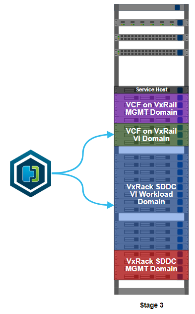
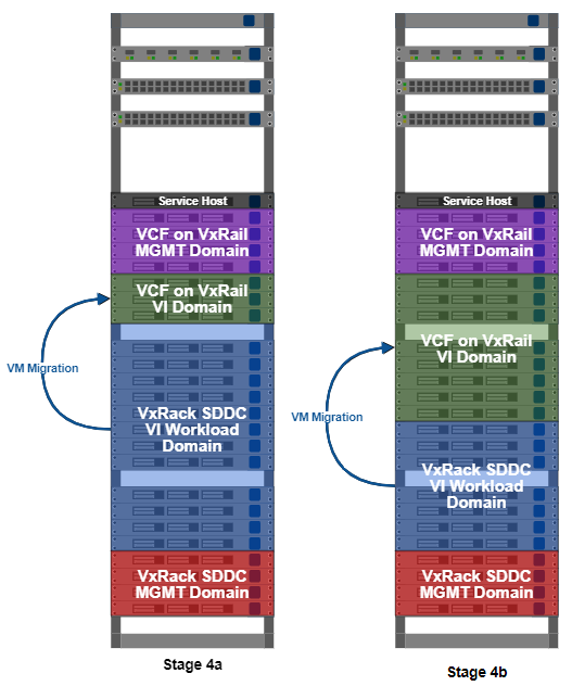
This is stage 3 of the build, HCX installation. I’ve worked out what VMs I can migrate to allow me to free up some more resources on the VxRack. Moving some VMs off the VxRack will allow me to decommission and convert more nodes, then add more capacity to my VCF on VxRail environment. In something of a departure from the deployment norm, the installation starts on the migration destination, not the source.

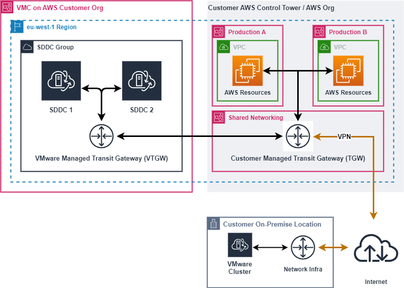
There is something I need to cover up front, lest it cause mass hysteria and confusion when I casually refer to it further down in this post. ‘Source’ and ‘destination’ are somewhat interchangeable concepts here. Usually, you’d move something from a source to a destination. With HCX, you also have the option of reverse migration. You can move from a destination to a source. Using HCX as a one-time migration tool from VxRack SDDC to VCF on VxRail, it doesn’t matter too much which clusters are my source or destination. If I intended to use HCX with other clusters in the future, or with a service like VMware Cloud on AWS, I’d probably put my source on a VxRail cluster and my first destination on VxRack SDDC. Also important here is that one source appliance can link to several destinations.

Back to the install. The HCX installer OVA is deployed on the VxRail VI workload domain that I created in the last part. The deployment is like any other. I set my management network port group and give the wizard some IP and DNS details for the appliance. The host name of the appliance is already in DNS. After the deployment the VM is powered on, then left it for about 5 minutes to allow all services to start up. As you might expect, attempting to load the UI before everything has properly started up will result in an error. When it’s ready to go, I’ll open up https://[DESTINATION-FQDN]:9443 in my browser and login at the HCX Manager login prompt.

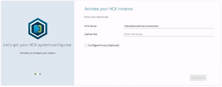
The initial config wizard will is displayed, and it’s quite a painless process. It’s notable though that internet access is needed to configure the HCX appliance. Proxy server support is available. I enter my NSX enterprise plus license key, leaving the HCX server URL at it’s default value.

HCX license entry and activation.

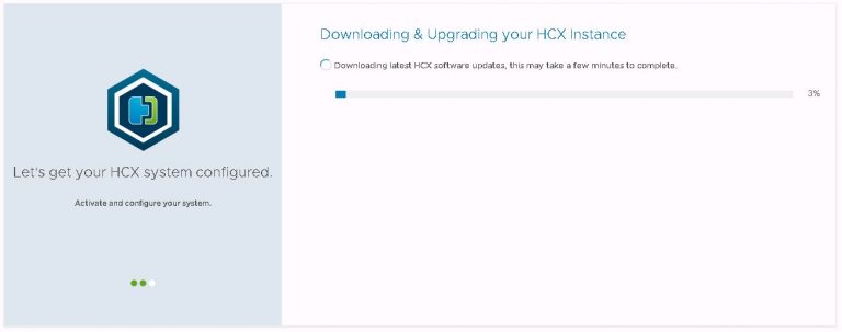
Click the activate button and as I didn’t deploy the latest and greatest HCX build, a download & upgrade process begins. This takes several minutes, the appliance reboots at the end to activate the update. Your mileage will no doubt vary, depending on the speed of the internet connection you’re working on.

HCX automatic download and upgrade

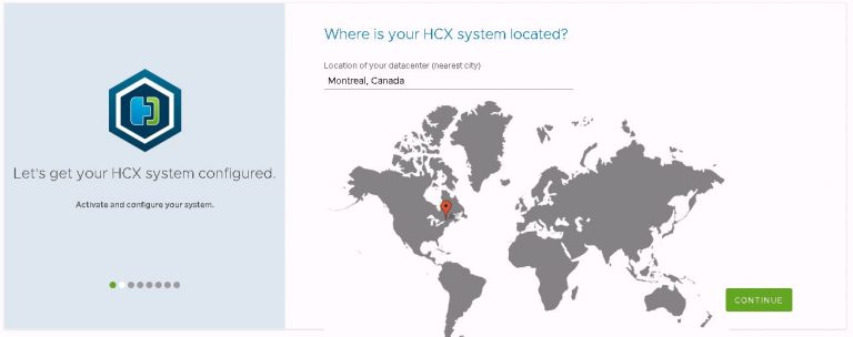
After the reboot, log back in at the same URL to continue the configuration. The next part involves picking a geographic location for your cluster. Feel free to be as imaginative as you like here. With all my clusters in the same physical location, I decided to take artistic license.

Location of the HCX destination cluster.

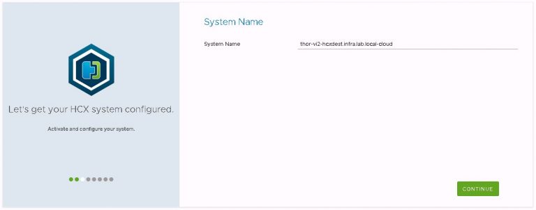
System name stays at the default, which is the FQDN with “cloud” tagged onto the end. 

HCX system name

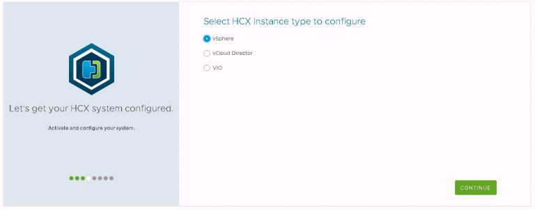
“vSphere” is the instance type I’m configuring. Interestingly, VIO support appears to have been added in the very recent past and is now included in the instance type list.

HCX instance type

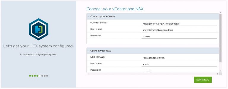
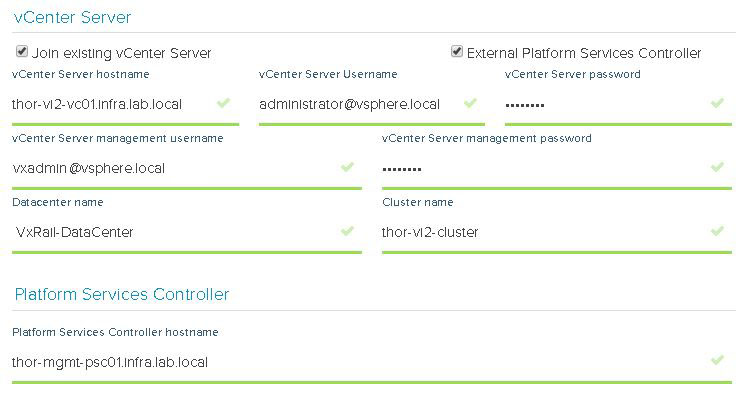
Next up is login details for my VI workload domain vCenter and NSX manager instances.

HCX connection to vCenter and NSX

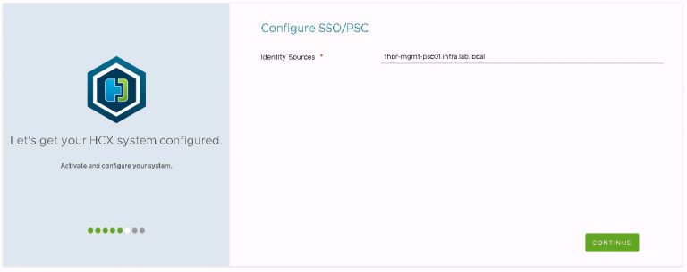
After which, the FQDN of the first PSC in the VCF management cluster.

HCX connection to external PSC

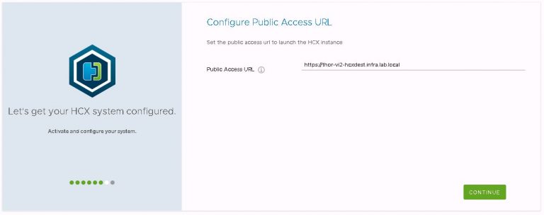
Then set the public access URL for the appliance/site. To avoid complications and potential for confusion down the road, this is set to the FQDN of the appliance.

HCX public access URL

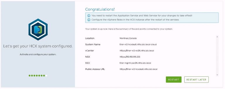
Finally is the now ubiquitous review dialog. Make sure all the settings are correct, then restart for the config to be made active.

Completed HCX initial setup

After the restart completes, additional vSphere roles can be mapped to HCX groups if necessary. The SSO administrators group is added as HCX system administrator by default, and that’s good enough for what I’m doing. This option is located within the configuration tab at the top of the screen. Then under vSphere role mapping from the left side menu.

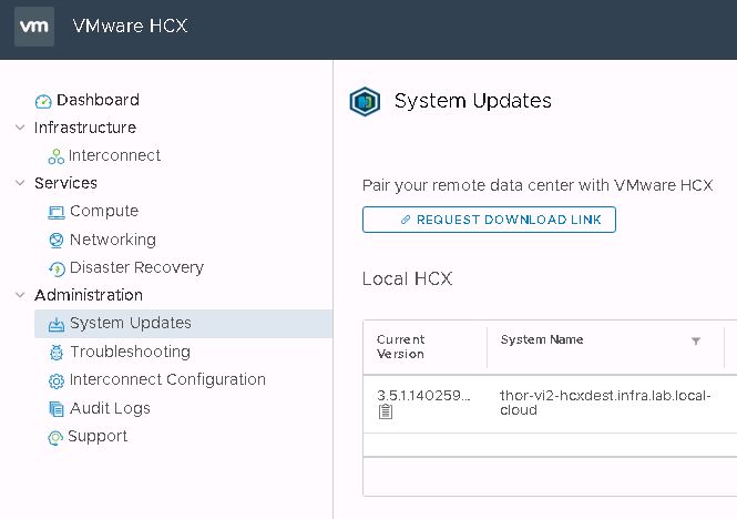
Deploying the OVA on the destination gives you what HCX call a “Cloud” appliance. The other side of the HCX partnership is the “Enterprise” appliance. This is what I’m deploying on the VxRack SDDC VI workload domain. This is another potential source of confusion for those new to HCX. The enterprise OVA is sourced from within the cloud appliance UI. You click a button to generate a link, from which you download the OVA. To find this button, log out of the HCX manager, then drop the :9443 from the URL and log back in using SSO administrator credentials. Go to the system updates menu and click “Request Download Link”.

Requesting a download link for HCX Enterprise OVA

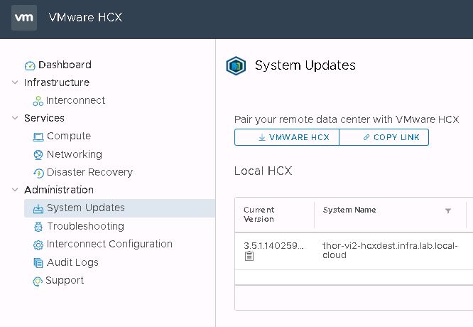
It may take a few seconds to generate the link, but the button will change to either allow you to copy the link or download the enterprise OVA directly.

HCX Enterprise OVA download link

I didn’t do this the first time around, because of an acute aversion to RTFM. Instead, I installed cloud and enterprise appliances that were of slightly different builds and ultimately, they did not cooperate. The site link came up just fine, I just wound up with VMs that would only migrate in one direction and lots of weird error messages referencing JSON issues.

The freshly downloaded enterprise appliance OVA gets deployed on the VxRack, and goes through much the same activation and initial configuration process as the cloud appliance did.

HCX had two methods of pairing sites. In fact, it has two. The regular “Interconnect” method and the new “Multi-Site Service Mesh”. The second is more complicated to set up, but the first is deprecated. So I guess the choice has been made for me.

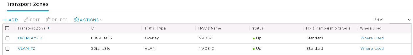
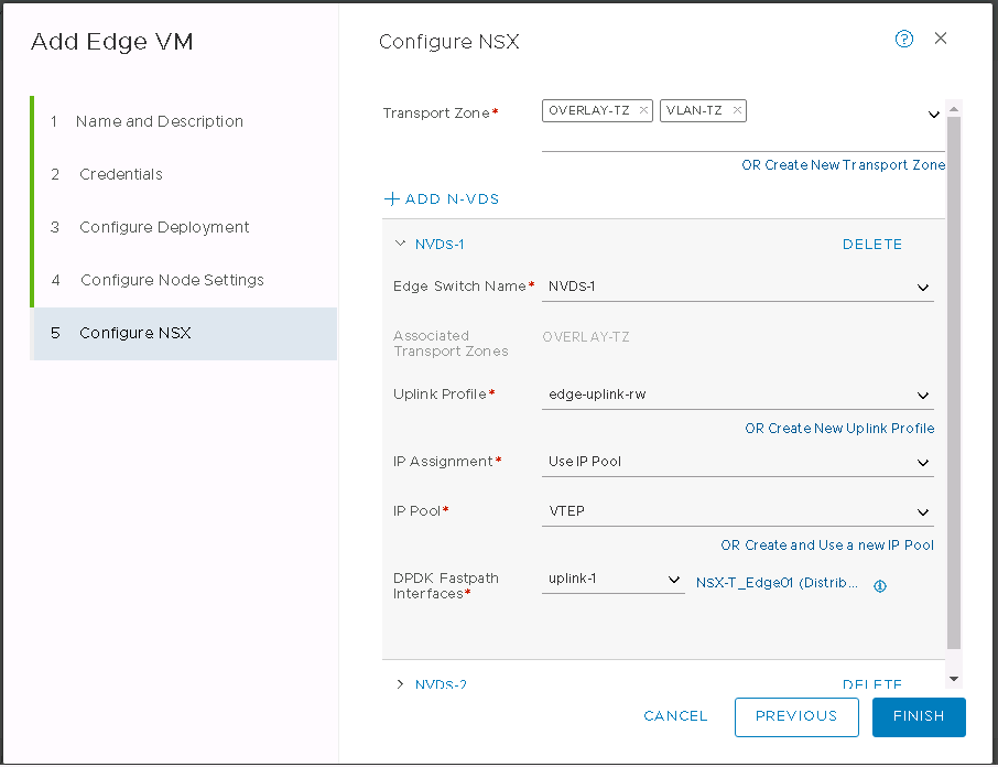
Before I get to linking sites however, I need to create some profiles. This happens on both the cloud and the enterprise sites in an identical manner. I’ll create one compute profile per site, each containing three network profiles. The compute profile collects information on vSphere constructs such as datacenter, cluster and vSAN datastore. The network profiles are for my management, uplink and vMotion networks.

Still within the HCX UI, I move over to the interconnect menu under the infrastructure heading. The first prompt I get is to create a compute profile. I’ll try to make this less screenshot heavy than the above section.

1. First, give the compute profile a name. Something descriptive so it won’t end up needle in a haystack of other compute profiles or service names. I name mine after the vSphere cluster it’s serving.

2. In services, I deselect a couple of options because I know I’m not going to use them. Those are network extension service and disaster recovery service. All others relate to migration services I’m going to need.

3. On the service resources screen, my VI workload domain data center and vSphere cluster are selected by default.

4. All I need to select on the deployment resources screen is the vSAN datastore relevant for this cluster. Only the resources within this cluster are displayed.

5. Now I get to the first of my network profiles, so back to the screenshots.

In the drop down menu for management network profile, click create network profile.

HCX service mesh network profile creation

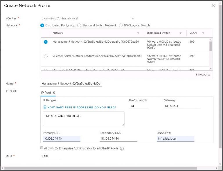
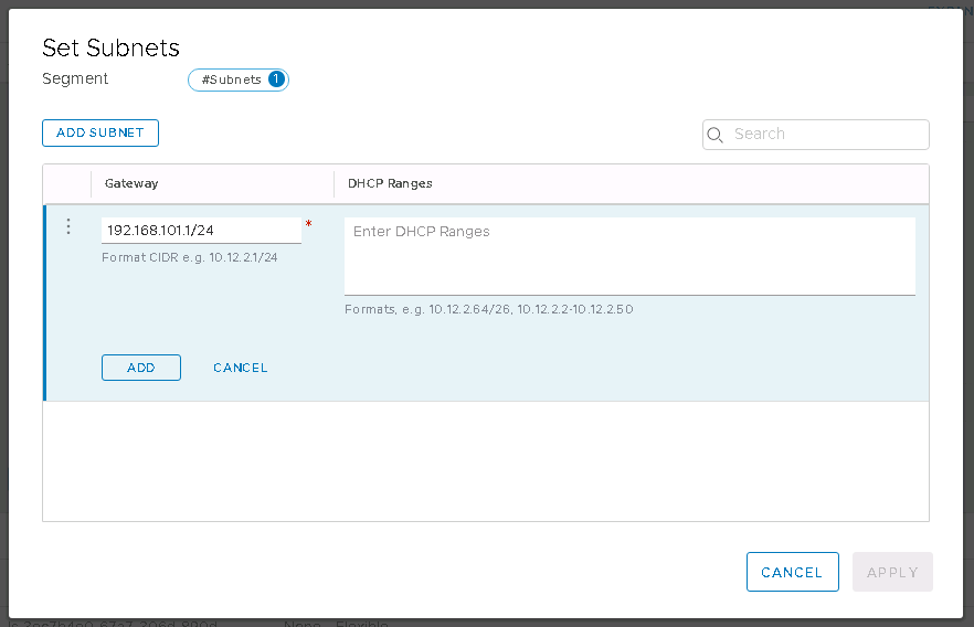
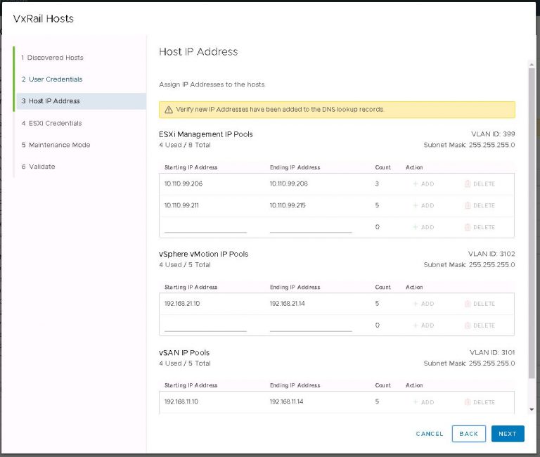
Each network profile contains an IP pool, the size of which will vary depending on the quantity and complexity of services you want to set up. In my case, not very many or very complicated; each IP pool got just 2 addresses.

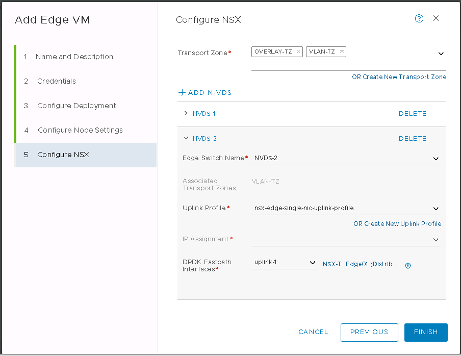
But wait a second, my uplink network profile is probably a little misleading. As I’m reusing the same IP subnet for the new environment, I created a management network profile with a sufficiently large IP pool to also serve as the uplink profile. So really, my management network profile got 4 IP addresses. I lied. Sorry about that.

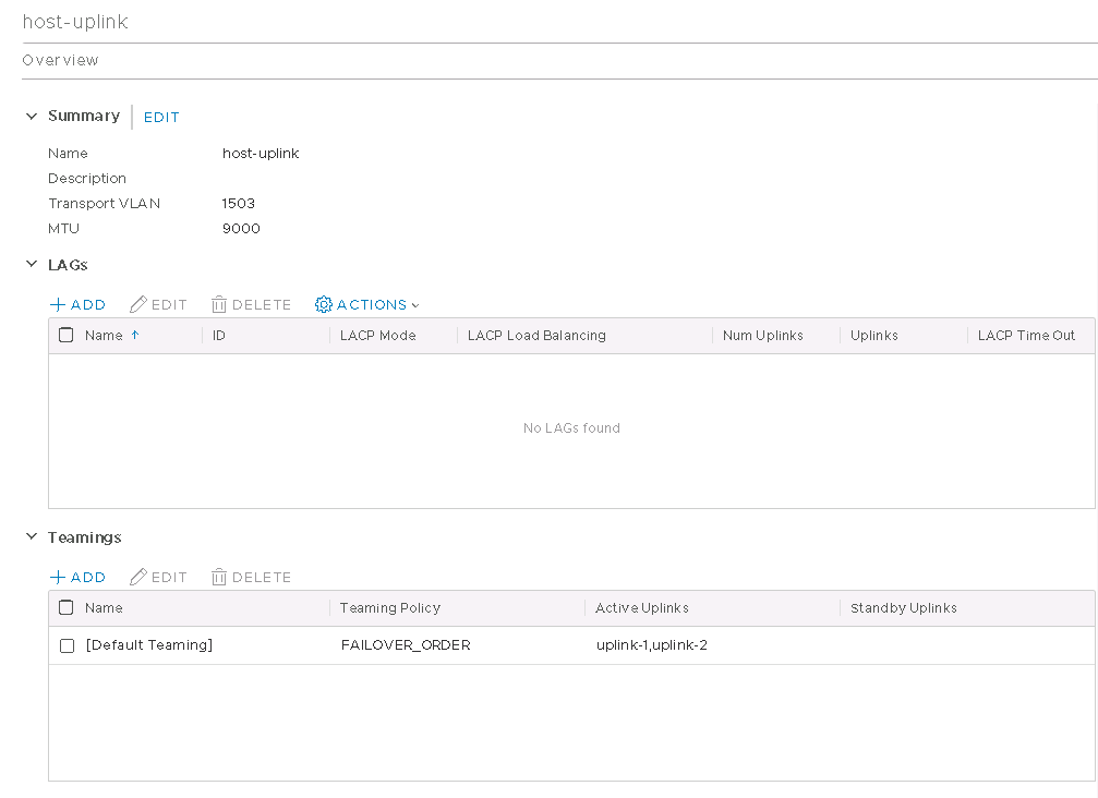
The uplink profile might be a separate VLAN with an entirely different IP subnet to act as a transit network between the VxRack and VxRail. In my case, they’re on the same physical switches so that seems a little redundant. If my source and destination were in two different physical locations, my uplink port group would be using public IP addressing within my organization’s WAN. On that subject, there are ports that need to be open for this to work, but it’s nothing too out of the ordinary. TCP 443 and UDP 500 & 4500. Not a concern for me, as I have no firewalling in place between source and destination.

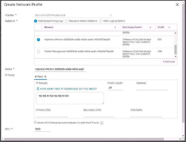
Finally I’ll create a vMotion network profile using the same process as the management network profile. I don’t have a default gateway on the vMotion VLAN, so I left that blank along with DNS information.

HCX service mesh network profile creation

Next up is vSphere replication, and the management network profile is selected by default. Connection rules are generated, which is of concern if firewalls exist between source and destination. Otherwise, continue and then click finish to complete the compute profile on the destination.

Now do the exact same thing on the source appliance.

With all the profiles in place, I’ll move on to setting up the link. That is accomplished on the source appliance (or HCX plugin within vSphere web client) by entering the public access URL which was setup during the deployment of the cloud appliance, along with an SSO user that has been granted a sufficiently elevated role on the HCX appliance. Keeping things simple, I left it with the default administrator account. I’ll complete everything below from within the HCX source appliance UI.

First up, I’ll import the destination SSL certificate into the source appliance. If I don’t do this now, I’ll get an error when trying to link the sites in the next step. This is done by logging into the source appliance at https://[SOURCE-FQDN]:9443, clicking on the administration menu and then the trusted CA certificate menu. Click import and enter the FQDN of the destination appliance.

HCX import destination appliance certificate

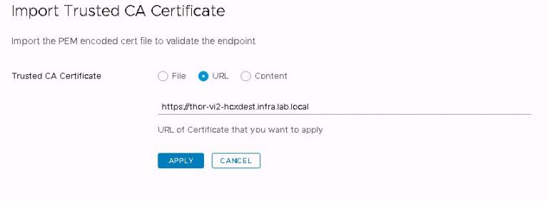
After clicking apply, I get a success message and the certificate is listed. With source and destination clusters sharing the same SSL root, the amount of setup I need to do with certificates is minimal. If I was migrating VMs across different trusted roots, I’d need a lot more to get it working. I’m not covering it here, mostly because I couldn’t explain it any better than Ken has already done on his blog.

Within the interconnect menu, open site pairing and click on the “Add a Site Pairing” button. Enter the public access URL of the destination site (remember I set it as the FQDN of the destination) and also enter a username and password for an SSO administrator account.

HCX site pairing dialog

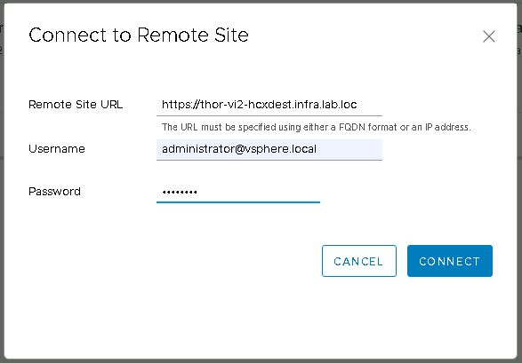
If everything up to this point has been configured correctly, the site pairing will be created and then displayed.

HCX site pairing display

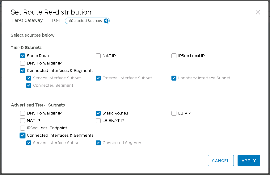
On the home stretch now, so I’m moving on to the service mesh. Within the service mesh menu, click on “Create Service Mesh”. The source appliance will be selected, click the drop down next to this to select the destination appliance. Now select compute profiles on both sites. Services to be enabled are shown. As expected, I’m missing the two I deselected during the compute profile creation. I could at this point choose entirely different network profiles if I wished. I don’t want to override the profiles created during the compute profile creation, so I don’t select anything here. The bandwidth limit for WAN optimization stays at it’s default 10Gbit/s. Finally a topology review and I’m done with service mesh. Except not quite yet. I’ll give it a name, then click finish.

The service mesh will be displayed and I’ll open up the tasks view to watch the deployment progress. But alas, it fails after a couple of minutes. Thankfully, the error message doesn’t mess around and points to the exact problem. I don’t have a multicast address pool set up on my new NSX manager.

HCX failed service mesh deployment

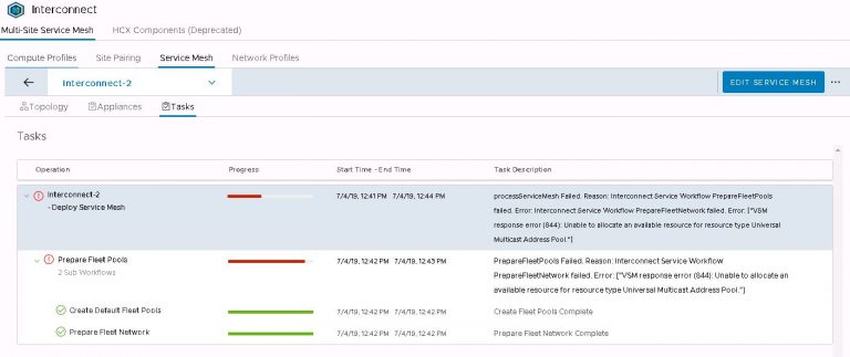
That’s an easy one to fix. In vSphere web client, jump over to the NSX dashboard by selecting networking and security from the menu. Then into installation and upgrade and finally logical network settings. Click on edit under segment IDs. Enable multicast addressing and give it a pool of addresses that doesn’t overlap with any other pool configured on any other instance of NSX that may be installed on VxRail or VxRack clusters.

NSX segment ID settings

With that minor issue resolved, I go back to the HCX UI and edit the failed service mesh. Step through the dialog again (not changing anything) and hit finish. Now I’m back to watching the tasks view. This time it’s entirely more successful.

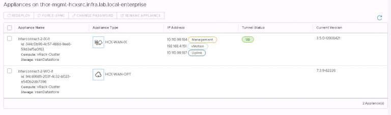
The above configuration deploys two VMs per site to the cluster and vSAN datastore chosen in the compute profile. A single, standalone ‘host’ (like a host, but more virtual) is added per site to facilitate the tunnel between sites.

Leaving the newly deployed service mesh to settle and do it’s thing for a few minutes, I returned to see that the services I chose to deploy are all showing up. Viewing the interconnect appliance status shows that the tunnel between the sites is up.

HCX appliance and tunnel status

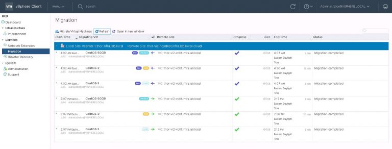
In the vSphere web client, it’s time to test that tunnel and see if I can do some migrations. The HCX plugin is available in the menu, and the dashboard shows our site pairing and other useful info.

Into the migration menu and click on “Migrate Virtual Machines”. Because I don’t really want to have to migrate them one by one. I could have done that by right clicking on each VM and making use of the “HCX Actions” menu. That was labeled “Hybridity Actions” when I was running an earlier version. I imagine that was like nails on a chalkboard to the UX people.

Inside the migrate virtual machines dialog, my remote site is already selected. If I had more than one (when I have more than one), I’ll need to select it before I can go any further. I’m going to migrate three test VMs from the VxRack SDDC to the VxRail VI workload domain, using each of the three available migration options. Those are vMotion, bulk and cold.

The majority of my destination settings are the same, so I set default options which will be applied to VMs chosen from the list. The only things I’ll need to select when picking individual VMs is the destination network and either bulk or vMotion migration.

HCX VM migration dialog

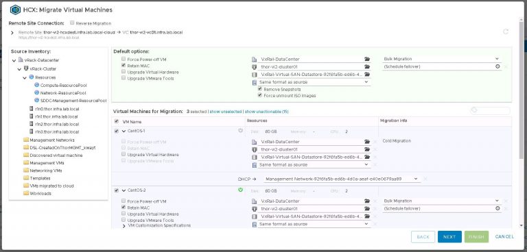
A little info on migration options. When I select a powered off VM, cold migration is the only available option. For powered on VMs, I can choose bulk or vMotion. The difference being that vMotion (much like a local vMotion) will move the VM immediately with little to no downtime. Bulk migration has the added benefit of being able to select a maintenance window. That being, a time when the VM will be cut over to the destination site. Very useful for, as the name suggests, migrating VMs in bulk.

With all my options set, I advance to the validation screen. Unsurprisingly, its telling me that my vMotion might get affected because of other migrations happening at the same time. My bulk migration might need to reboot the VM because my installation of VMware tools is out of date. As this is a test, I’m not going to worry about it.

HCX VM migration status

As you’d expect, vMotion requires CPU compatibility between clusters. Not an issue for me, because I’m reusing the same hosts so all of the nodes have Intel Xeon 2600’s. If this wasn’t the case, I’d have ended up enabling EVC. But better to figure out any incompatibility up front because enabling EVC once you’ve got VMs already on the cluster isn’t a trivial matter. Also on this subject, be aware that when a VxRail cluster is built, EVC will be on by default. I already turned it off within my destination VxRail cluster. 

I’m going to go out on a limb and guess that bulk migration is the one I’ll end up using the most. That way, I can schedule multiple VMs during the day and set my maintenance window at the same time. Data will be replicated there and then, with VM cutover only happening later on in the maintenance window. Great for those VMs that I can take a small amount of downtime on, knowing it’ll be back up on the VxRail in the time it takes to reboot the VM.

Second will probably be cold migration, for those VMs that I care so little about that I’ve already powered them off on the VxRack. Any high maintenance VMs will get the vMotion treatment, but still certainly within a brief maintenance window. HCX may whine at me for VMware tools being out of date on (some) most of the VMs, so I’ll either upgrade tools or deal with HCX potentially needing to bulk migrate and reboot those VMs in order to move them.

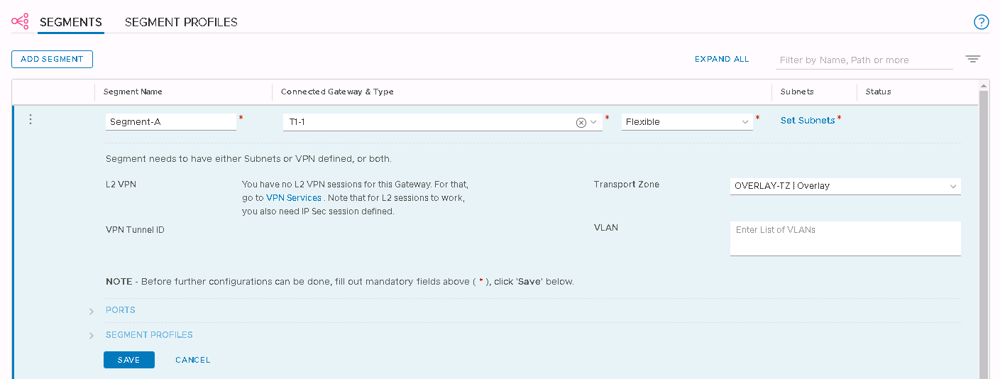
As to why I left two services out of the service mesh, I won’t be using HCX in a disaster recovery scenario and I won’t be extending any layer 2 networks. The VxRack and VxRail share top of rack switching, so any and all important L2 networks will be trunked to the VxRail and have port groups created. 

That’s certainly leading on to a much larger conversation about networking and VLAN or VXLAN use. Both the VxRack SDDC and VCF on VxRail clusters have NSX installed by default, and I’m using NSX backed networks for some of my VMs. I’ll get to that in the near future as a kind of addendum to this process.

So;

How long is it going to take? – I was just a little under 2 days total before I touched HCX. A single source and destination install, along with configuration and site pairing could make up the rest of day 2. All that takes about 90 minutes.

And;

How much of it can be automated? – Depending on your chosen deployment strategy, HCX could be a one-time install. Given the relatively short time it takes to install (plus the potential for errors as we’ve seen above) makes it a hard sell for automation.

With HCX installed and running, I can move onward. Out of the frying pan and into the fire. Getting some of those production VMs moving.

Convertible Cloud: VxRack SDDC to VCF on VxRail, Part 2

Quick Links
Part 1: Building the VCF on VxRail management cluster
Part 2: Virtual Infrastructure Workload Domain creation
Part 3: Deploy, Configure and Test VMware HCX
Part 4: Expanding Workload Domains

Following on from part 1, I’ve now got a four node VxRail cluster running all the required VCF management VMs. As I’m converting an entire VxRack, I’m not using the consolidated architecture. In that design, management and workload/production VMs are run on the same cluster. It’s meant for small environments of up to about six nodes. Anything beyond that falls into the standard architecture model. So right now, technically I can’t run any production VMs on my VCF on VxRail deployment. Enter stage 2 of the process.

In stage 2, I’ll steal another three nodes from the VxRack SDDC workload domain, decommission them, convert them to VxRail nodes and build another cluster. Except there’s a little bit more to it than that.

In an ideal automated world, I’d have finished up day one by decommissioning the nodes I need for this stage of the build and kicking off the automation to convert them. Then when I get into the office at the start of day 2, I’ve got three freshly converted VxRail nodes waiting to be built. It needn’t be only three nodes of course. If I could have freed up more than that from my VxRack SDDC workload domain, I’d have decommissioned as many as I could have realistically gotten away with. Just enough to leave the production workload running (with some overhead of course) and enough not to violate any vSAN storage policies. The more nodes I can free up and convert now, the less iterations of convert & build I need to do in the future.

Without automation converting the nodes, I’m looking at just under half of day 2 to get the three nodes where they need to be. I’m going to base the timing at the end of this post on a non-automated process.

Once I kick off the RASR reset on all three nodes, I know I’ve got some time to spend elsewhere. So I log into VxRail SDDC manager and create a VI workload domain. This is a little different than how you’d create one in VxRack SDDC world. There you’d pick nodes out of the pool, give the wizard some details and it’d build your cluster for you. In VCF on VxRail, we haven’t yet got the nodes to create the cluster with. So we more or less half create the VI workload domain and then add the cluster of nodes afterward. I’ll move on from my gross oversimplification and instead show you the process.

Log into SDDC manager, find the Workload Domain button and click it. Choose the only selectable option, ‘VI – VxRail Virtual Infrastructure Setup’.

I gave my new workload domain the imaginative name ‘WorkloadDomain2’. Next, give vCenter details.

The vCenter doesn’t exist yet of course, an empty one will be deployed by SDDC manager which you’ll build your VxRail cluster into. The vCenter DNS name I provided here was already set up on the DNS server.

Review all the details entered and click finish. The SDDC dashboard will reappear and the progress of the vCenter deployment is shown in the tasks view at the bottom of the UI. It may be hidden, there are buttons at the bottom right of the window that’ll expand or maximise the tasks view.

About 15 minutes later it was done and I had a new vCenter in my list with only a datacenter created within it. Once this process finishes, the new VI workload domain will display in the dashboard, but will show a status of activating.

It’ll continue to show this status until the VxRail cluster is added and the domain creation is completed. So I’ll get onto that next.

With the RASR reset finished up on the three nodes, I rebooted to the IDSDM and kicked off the factory reset. This is quick in comparison to the RASR reset and when it’s done, I rebooted the nodes so the automated build would kick off. While that’s in progress, I copied the switch config applied to the ports for the management nodes and also applied it to the ports for these three nodes.

I went through my usual prep for VxRail cluster build (briefly covered that in part 1), then kicked off the install. The only difference this time is that I’ve already got a vCenter deployed for this cluster, so I choose to join an existing vCenter and use an external PSC.

As in the management cluster build, I’m also selecting ‘None’ for the logging option.

I entered all the other usual details, validation passed and started the cluster build. It finished up quite quickly and I was back into SDDC manager to complete the VI workload domain creation.

Within the workload domains menu, I chose my currently ‘activating’ WorkloadDomain2 and selected “Add VxRail Cluster” from the actions menu.

The cluster addition dialog opens up, and after a few seconds displayed the VxRail cluster I just finished building.

I entered the host password and clicked “copy to all hosts”. Probably more of a time saver if I was building a huge cluster.

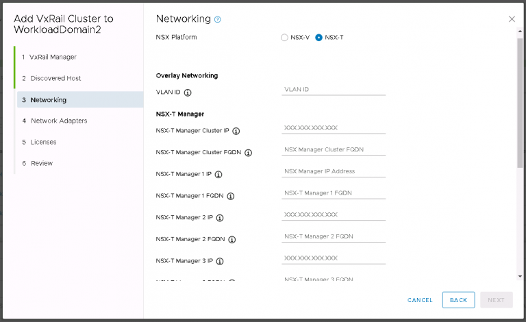
Next up is NSX settings. Very self-explanatory, nothing out of the ordinary here. I entered my VXLAN VLAN ID and some IP settings for both the NSX manager and controller cluster.

Moving on to licenses, which in my case were automatically populated from those I entered right after the SDDC bringup. Within the SDDC UI, go to Administration > Licensing.

Finally, the now familiar review screen. I clicked finish and the second half of the VI workload domain creation started.

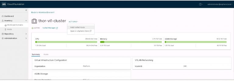
I monitored the progress in the SDDC manager tasks view. It took about 40 minutes to run the cluster addition tasks and display my new VI workload domain in SDDC manager.

Logging into vCenter, I can see that my cluster is present and NSX has been deployed & configured.

Of course, the cluster is a little empty right now, containing only the NSX controllers and VxRail Manager. I’m going to change that in part 3 when I deploy HCX and run some test migrations from the VxRack SDDC.

Briefly back to one of the questions asked at the start of part 1;

  1. How long is it going to take? – Total so far is the best part of 2 days. Although I only used three nodes to create my first VI workload domain, I could have built it with many more. It would not have added a significant time penalty to the process of creating and finalising the workload domain. The penalty there would have been the additional time to convert the nodes in the first place.