VMware Cloud on AWS; SDDC Groups & Advanced Connectivity

Now that we’ve got our first SDDC up and running with a VPN connection back to our office/data center, it’s time to tear it all down again and turn it into something a little more useful. I need to define the word useful before I go on, because this isn’t going to be a topology that everyone wants or needs. It’s simply a demo of what you can do with SDDC and AWS at scale. If you have multiple SDDCs in a region or across multiple regions and need them to communicate with multiple AWS accounts (possibly managed by AWS Control Tower), then this will be relevant for you. Or if like me you’re a networking nerd and just want to see something cool, read on.

This can obviously also work on a smaller scale, but as some of the components I’ll be deploying will lead to increased AWS charges, there’s likely to be a cheaper way to accomplish your goals if you have a smaller environment.

For reference as we move through this exercise, the below diagram is roughly the end state I want for my environment.

On the left side of the diagram is where our VMware Cloud components live. Right now we’ve just got a single SDDC so I’ll be creating a SDDC group and adding our SDDC to it. The functionality of an SDDC group goes well beyond what we’ll be doing here. It can connect multiple SDDCs together via high bandwidth, low latency links (what VMware calls “Transit Connect”) across up to three AWS regions. SDDC groups can only be formed with SDDCs that are within the same VMC organisation. If your intention isn’t to peer with an AWS account, you can also connect an AWS Direct Connect link to an SDDC group.

Getting back to our scenario, on the right side of the diagram is our existing AWS infrastructure. We’ve got AWS Control Tower setup and to keep things neat and tidy I’ve got a ‘Network Shared Services’ account where all the network interconnects terminate and where our transit gateway is setup. I’ve also got a couple of other accounts running various workloads. Some production, test & dev, sandbox, stuff like that. In some cases we’ve got VPCs created in our network account shared to those accounts and other accounts are free to create their own VPCs and request to attach them to the transit gateway in the networking account.

The bottom of the diagram is the easiest part. I’ve got a VMware cluster on-premises which is currently attached to the AWS transit gateway using a route based VPN connection. If I was in need of more bandwidth or lower latency than a VPN could provide, I’d look at a direct connect (or multiple direct connects for redundancy).

With all that covered, lets launch into the demo.

We start off pretty basic by creating the SDDC group, then things get a little more complicated. To establish the peering between the VMware managed TGW and our TGW, I needed to provide the account number where the TGW is located and the ID of the TGW itself. I then needed to accept the peering request manually. I haven’t enabled auto-accept on the TGW and unless you’d happily give a set of your house keys to everyone that has access to your AWS organisation, you shouldn’t either. The potential for chaos on a grand scale is just too much of a risk to accept.

With that done, I decided to create a prefix list with VMC. That will make routing updates a little easier. A prefix list creates an aggregated list of all network routes from the VMC compute gateway and shares it with the AWS account you specify. So instead of manually adding/removing a route every time you add a new or remove an old segment on VMC, the prefix list will take care of it and ensure our transit gateway has an up to date routing table. Better still, because we’re running BGP over the VPN the routing updates will also be pushed down to the on-premises router without us having to do anything.

To finish up the VMC prefix list setup, I need to accept the resource share from VMC. I then need to create a reference in the transit gateway routing table for it. That’s it. Almost no effort to have dynamic routing everywhere.

After creating the necessary firewall rules within the SDDC, I have full connectivity to my AWS accounts and my SDDCs from on-premises via a single VPN connection. I also have bi-directional connectivity from all of my AWS accounts to my SDDC. A new segment created in the VMC console is immediately pushed to the SDDC vCenter and almost immediately pushed to the AWS and on-premises routing tables. Temper your expectations, it is BGP after all.

The networking is now complete and like all good projects, my introductory journey into VMware Cloud on AWS is experiencing some scope creep. So stay tuned for part three of my two part series, in which I’ll cover the full setup of VMware HCX from my on-premises cluster to my VMC SDDC and migrate some VMs to the cloud.

VMware Cloud on AWS; Getting up and running

I make no bones about being a reformed server hugger. One of my more recent catchphrases is “I’d be a happy man if I never had to build another physical server spec”. So for those currently in the VMware ecosystem, I’ve been turning a lot of attention toward VMware Cloud on various hyperscalers. There is a particular emphasis on AWS and Azure here. GCP is also available, I just don’t get asked about it a lot. Sorry Google.

Some of the most frequent questions I hear include topics such as difficulty to setup and maintain the platform, required knowledge of the underlying hyperscaler, the ubiquitous horror of “vendor lock-in”, and of course the overall cost of the solution. The latter is a whole series of articles in itself, so I’ll be tactically dodging that one here. The short answer, as it so often is, is “it depends”.

Another frequently asked question surrounds the whole idea of “why should I be in the cloud”. There are quite a few well documented use cases for VMware Cloud. The usual ones like disaster recovery, virtual desktop, datacenter extension or even full on cloud migration. One that’s sometimes overlooked is that because SDDCs are so quick to spin up and can be done so with on-demand pricing, they’re great for short lived test environments. Usually, you can create an SDDC, get connectivity to it and be in a position to migrate VMs from your on-premises cluster or DR solution within a couple of hours. No servers to rack, no software to install, no network ports to configure, no week long change control process to trundle through.

For those organisations currently using native cloud services, there are a whole load of additional use cases. Interaction with cloud native services, big data, AI/ML, containers, and many many more buzzwords.

What I can do is show you how quickly you can get a VMC on AWS SDDC spun up and ready for use. The process is largely the same for Azure VMware Solution, with the notable difference that the majority of the VMC interaction in Azure is done via the Azure console itself. The video below gives you an idea of what to expect when you get access to the VMC console and what creating a new SDDC on AWS looks like.

I’ve included some detail on setting up a route based VPN tunnel back to an on-premises device. Policy based and layer 2 VPN are also available, but as my device (a Ubiquiti Edgerouter) is BGP capable I’m taking what I consider to be the easy option. I prefer to use a route based VPN because it makes adding new networks easier and allows a great deal of control using all the usual BGP goodness any network team will be comfortable with. There is also some content covered for firewall rules, because as you might expect they are a core component of controlling access to your newly created SDDC.

Something you may immediately notice (although not explicitly demonstrated in the video) is that the only interaction I had with AWS native services throughout the SDDC creation was to link an existing AWS account to the SDDC. For those without AWS knowledge, this is an incredibly straightforward process with every step walked through in just enough detail. If you’re creating an SDDC, you need to link it to an AWS account. If you don’t already have an AWS account, it’ll take less than five minutes to create one.

The only other requirement right now is to know a little bit about your network topology. Depending on how complex you want to get with VMC on AWS in the future, you’ll need to know what your current AWS and/or on-premises networks look like so you can define a strategy for IP addressing. But of course even if you never plan on connecting the SDDC to anything, you should still have an IP addressing strategy so it doesn’t all go horribly wrong in the future when you need to connect two things you had no plan to connect when you built them.

The one exception I’ll call out for the above is self-contained test environments. What I’m thinking here is a small SDDC hosting some VMs to be tested and potentially linked to an AWS VPC which hosts testing tools, jumpboxes, etc on EC2. If this never touches the production network, fill your boots with all the overlapping IP addresses you could possibly ever need. In this case, creating an environment as close as possible to production is critical to get accurate test results. Naturally, there’s also a pretty decent argument to be made here for lifecycling these type of environments with your infrastructure as code tool of choice.

On that subject, how do you connect a newly created SDDC to an AWS VPC?

This is the process at it’s most basic. Connecting a single VMC SDDC to a single AWS VPC in a linked AWS account. Great for the scenario above where you have self-contained test environments. Not so good if you have multiple production SDDCs in one or more AWS region and several AWS accounts you want them to talk to. For that, we’ve got SDDC groups and transit gateways. That’s where the networking gets a little fancier and we’ll cover that in the next post.

I hope by now I’ve shown that a VMC on AWS SDDC is relatively easy to create and with a bit of help from your network team or ISP, very easy to connect to and start actively using. I’ve tried to keep connectivity pretty basic so far with VPN. If you are already in the AWS ecosystem and are using one or more direct connect links, VMC ties in nicely with that too.

The concept of vendor lock-in comes up more than once here. It’s also something that’s come up repeatedly since Broadcom appeared on the VMware scene. To what extent do you consider yourself locked-in to using VMware and more importantly, what are the alternatives and would you feel any less locked-in to those if you had to do a full lift & shift to a new platform? If you went through the long and expensive process to go cloud native, would going multi-cloud solve your lock-in anxiety? Are all these questions making you break out in a cold sweat?

If you take nothing else away from all the above, I hope you’ve seen that despite some minor hyperscaler platform differences, VMware Cloud is the same VMware platform you’re using on-premises so there is no cloud learning curve for your VMware administrators. You can connect it to your on-premises clusters and use it seamlessly as an extension of your existing infrastructure. You can spin it up on demand and scale up and down hosts quickly if you need disaster recovery. You can test sensitive production apps and environments in isolation.

As I brought up those ‘minor hyperscaler differences’, how would they impact your choice to go with VMC on AWS, Azure VMware Solution, GCP, or another provider? As the VMware product is largely the same on any of the above, it comes down to what relationship you currently have (if any) with the cloud provider. The various providers will have different VMC server specs and connectivity options which would need to be properly accounted for depending on what your use case is for VMC. This is another instance of it being a whole topic by itself. If you’re curious, the comment box is below for your questions.

In the next post on this subject I’ll go into more detail about some complex networking and bring in the concept of SDDC groups, transit connect and AWS transit gateways. I’ll also cover a full end-to-end HCX demo in the next post, so you’ll have what is possibly the best way (in my biased opinion anyway) of getting your VMs into VMware Cloud on AWS.

VMware HCX; Testing the limits

Introduction

I had a conversation with a colleague recently about VMware HCX, specifically around network requirements and the minimum link specifications we’d need to have between two sites so that the basic functionality would work as intended.

I threw out a figure that I knew was well in excess of what would be required for HCX (and all the other services that need to be run over the link) but it got me thinking; How bad could the link get before even basic HCX services would just stop working?

I was a little surprised to read the figures in the below table from the VMware docs site and I’ve highlighted the numbers I’m interested in for HCX vMotion. The bandwidth figure listed is quite a bit lower than I thought would be recommended. I’m even more surprised by the latency figure, quite a lot higher than I imagined HCX would endure.

With the above in mind, lets see what it takes to break HCX.

The Lab

But first, this. My test environment consists of two VxRail clusters running on 13G nodes with version 7.x code. Networking is 10G everywhere and between the two sites I’ve got a Netropy 10G link emulator to provide all the link state related horror later on. As HCX encapsulates traffic within a tunnel between sites, the traffic inspection options in the Netropy are going to be less useful to me to be able to pull specific traffic off a link. Instead, I’ve done my best to isolate all HCX traffic to a single 10G NIC on each cluster. In all migration tests, I’m using clones of an 80GB Windows 2012 VM.

I should also point out that this is by no means a benchmark, nor should it be interpreted as such. I was merely curious at what point HCX would stop working in my existing lab environment. The test environment hasn’t been endlessly tweaked for maximum vMotion performance. It’s pretty much a straight out of the box VxRail build.

We already know that a 10G link with very little latency is going to work just fine and yes I did run a migration to test that.

The transfer speed axis is a little bit of an eye chart, but it’s within 2.3 to 2.6Gbps. The transfer did initially spike to 6.8Gbps, but it settled to it’s final figure pretty quickly.

Testing VMware minimums

With that out of the way, lets get straight to the VMware quoted minimums. I modified the link characteristics of the Netropy to 100Mbps with a fixed 150ms of latency. In the screenshot below, 75ms is applied in each direction for a total of 150ms for the round trip.

At this new setting the response time of the HCX dialogs within vSphere client are somewhat slower, taking marginally longer to refresh and gather cluster information from the remote site. Once all the information has been gathered though, the process of selecting migration options is just as quick as with a faster/lower latency link.

Once the migration kicked off, it did max out the available line-rate initially, only dropping to about 35Mbit after 60-70% of the migration had completed.

To migrate the entire 80GB VM took a little over 4 hours. While that time is far from ideal in a production environment, it becomes more acceptable depending on the frequency and quantity of migrations. Keep in mind also that it’s not exactly a tiny VM that I’m pushing around here. In a small production environment or one where mobility is restricted to disaster recovery scenarios (where the VMs would be kept in sync between sites according to RPO/RTO), it becomes almost workable.

Pushing the limits

But it’s still not broken, so I’m not done. What if instead of moving your VMs to the other side of the country, you’re moving them to the other side of the world. Lets keep the same 100Mbit link but ramp the latency to 300ms.

The most charitable thing I can say about the beginning of the process was that the migration dialog did eventually open. I measured the time it took to do that in one cup of coffee made & consumed, and several minor household tasks completed. Lets say 15-20 minutes. Like the previous attempt, once the dialog opened and information was pulled from the remote site, selecting all required migration options was snappy and responsive.

Unsurprisingly, further trouble is just around the corner and once I kicked off that migration, everything ground to a halt once again. The length of time that the base sync performed at the beginning of the migration took to complete was a sign that I probably shouldn’t wait around for live stats on this one. Before shutting down for the evening, I did see peak speeds of between 50 and 60Mbps reported by the Netropy device.

Today is tomorrow and the results are in.

If the text is small and hard to read, let me help. It’s 11 minutes (for the 10Gbit link) versus 6 hours and 18 minutes. Needless to say, if you’re moving VMs to and from a distant site, be that another private site or a VMware Cloud on AWS region and all you’ve got is a 100Mbit link, you’re probably going to reserve the use of vMotion for special occasions. In this scenario, bulk migration with scheduled switchover might be your best friend. Or at least a way to preserve your sanity.

Pushing Bandwidth

You know what I’m going to say next. Even taking the above dismal results into account, HCX still works on a 100Mbit link with 300ms latency. It’s still not broken. The territory I’m entering now is well within the realm of testing with a link that is of zero use for any kind of traffic. I’m more concerned with finding out what happens with low bandwidth right now, so I’ll drop the link speed significantly to 20Mbit and return the latency to the VMware recommended minimum of 150ms. I fully expect the migration to succeed, even if it does take a day to do so. Onward, and downward!

But not downward far enough it seems, the migration still completed successfully at 20Mbit/150ms. It did take over 16 hours mind you, but the end result is what matters here.

From here, I’m conflicted about taking the bandwidth any lower. If you’re thinking about multi-site private cloud or hybrid private/public deployment and you can’t get at least a 20Mbit link between your sites, it’s almost certainly time to re-evaluate the deployment plan. So lets say the minimum bandwidth test result is a resounding pass. Even if all that’s available is VMware’s minimum recommended of 100Mbit, it’s going to be sufficient to migrate VMs between sites with relative ease.

Pushing Latency

So instead, I’m going to bring the bandwidth available back to a very healthy 500Mbit and focus instead on two things; Latency and packet loss. First up is latency and as I’ve already shown that even 300ms (double the VMware quoted minimum) still results in a successful migration, I’m going to double the double to 600ms.

Despite the huge jump in bandwidth since the last run, the equally huge jump in latency is firmly putting the link back into the almost unusable territory. With the migration running, the charts are showing exactly that.

At peak, less than a fifth of the total bandwidth available is being used and the average use is less than half the peak. Nothing out of the ordinary for a link with such high constant latency. Accordingly, migration time is huge at just over 12 hours.

Dropping Packets

My last attempt to prevent HCX from doing it’s job is to introduce packet loss to the link. The VMware table at the top of the post specifies a maximum loss of 0.1%. This feels very like another worst case scenario kind of test. A high level of packet loss on any link isn’t something that would be tolerated. For this test, I’m going to remove the latency from the link, but maintain the 500Mbit bandwidth. I’m introducing 5% packet loss.

The results are nothing shocking. For anyone not familiar, packet loss with TCP traffic on a link will cause packet transmission issues and re-transmissions will happen, effectively slowing down any data transfers.

With 5% packet loss set, average bandwidth is a fraction of the potential 500Mbit link speed.

With no packet loss, practically the entire 500Mbit link is used.

As packet loss increases, the above downward trend would continue until the link is unusable. As with the other tests above, HCX appears no more sensitive to poor link quality than any other network traffic would be.

Conclusion

It has become apparent that HCX will perform adequately on any link that is of relatively decent quality. It continues to function with acceptable performance well below the recommended figures that VMware quote in documentation. As I have stated in the tests above, I would expect that if the link between sites functions then HCX will also function.

To put a little more of a ‘real world’ slant on this, I performed a simple latency test to several AWS regions in which it’s possible to run VMware Cloud services and therefore act as a hybrid cloud into which VMs can be migrated using HCX.

My test environment is located in eastern US, so latency to US regions is lowest. Keeping in mind that I tested all the way to 600ms of latency and had successful, albeit slow transfers, it makes any of the available regions above seem viable.

It is obviously not realistic to expect HCX to be able to perform any magic tricks and work well (or at all) over a link so poor that any other network traffic would have issues traversing. I am pleased that my proposition at the beginning of this post was incorrect. I assumed there would be a point at which a built-in timeout or process error would take the whole thing down and HCX would beg for a faster and more stable link. I also assumed that when that happened, I’d still be able to show that inter-site connectivity was up and somewhat functional outside of HCX.

A somewhat anticlimactic conclusion perhaps, but one that’ll be of great use for my next HCX conversation. At least now I know that when a colleague asks what kind of link they need for HCX, I can confidently answer “anything that works”.

Deploying Cloud Foundation 3.9.1 on VxRail; Part 6

Last and possibly least (as far as effort required) for the Cloud Foundation stack is to deploy vRealize Operations. Much like the Lifecycle Manager installation, this is relatively painless.

Similar to previous deployments, I’ve already reserved an IP address for all vROPs nodes I intend on deploying and created DNS records. I’ve also entered a license key for the install in SDDC Manager. I’m leaving the install (number and size of nodes deployed) at default. Same as last time, Operations will be deployed onto the pre-created Application Virtual Network.

As you’ll see from the video above, all I had to do was select the license key and enter the FQDNs for each component. At the end of the deployment, I connected the existing workload domain.

That’s pretty much it, nothing too exciting or demanding.

As I said at the start of this series, I’m now moving on to working almost exclusively with Cloud Foundation 4.0 on VxRail 7.0. Thanks to the introduction of new features in both versions, I’m hoping to be able to cover off a few more topics that I didn’t get to in 3.9.x on VxRail 4.5 and 4.7. Things like Kubernetes, external storage connectivity, more in-depth NSX-T configuration and hopefully some PowerOne integration.

Deploying Cloud Foundation 3.9.1 on VxRail; Parts 4 & 5

The next step is a relatively easy one. I’m going to deploy vRealize Lifecycle Manager so that in the steps that follow this, I can use it to deploy both vRealize Automation and vRealize Operations Manager.

As I’ve said above, vRealize Lifecycle Manager is a simple install. One of the prerequisites of course is to have the LCM installer on the system, something I’ve already done. I may have mentioned in previous parts that before I did anything else (right after I completed the SDDC bringup), I downloaded all the packages I knew I was going to need to run through this series. Those packages are; vCenter, NSX-V, vRealize LCM, vRealize Automation and vRealize Operations Manager. I also downloaded any patch or hotfix bundles available.

Another requirement is to have an IP set aside for the LCM VM and a DNS record created. The LCM VM will be deployed onto one of the SDDC application virtual networks which I covered in a previous part. When those two easy tasks are done, I can kick off the LCM deploy in the vRealize Suite menu in the SDDC interface. Side note, if at this stage I tried to deploy anything else (vRA, vROPS), I’d get a helpful error that I need to deploy LCM first.

Less talk, more video…

The deployment process is not a very involved one. Enter an FQDN for the LCM VM, a password for the system admin and root account and that’s pretty much it. Once the deployment is done, I can log into the LCM dashboard and see that the SDDC deployed vRealize Log Insight instance has already been imported into the LCM.

Having the full LCM functionality available is useful, but throughout the final two deployments I’m not going to be using it. Everything will be done from within the vRealize menu in the SDDC UI.

Which brings me onto part five of the series, vRealize Automation. I couldn’t very well just leave this post with a simple LCM install. vRA deployment is a much more detailed and potentially troublesome process. The list of prerequisites is, as you’d expect, quite a bit longer;

  1. IP addresses allocated and DNS records created for all VMs;
      3x vRA appliance VMs
      All Windows IaaS VMs – 2x manager, 2x web, 2x DEM worker and 2x agent.
      Windows SQL VM
  1. Windows VM OVA template built to vRA specifications. Info here on VMware docs.
  2. Multi-SAN certificate signing request generated. Info here on VMware docs.
  3. License key for vRA added to SDDC licenses.
  4. Installation package for vRA downloaded to SDDC.
  5. MS SQL server built and configured with vRA database.

As you’ll see in the video above, the process is quite detailed. Roughly;

  1. Select the appropriate vRA license key.
  2. Enter certificate information. I took the CSR generated above on the SDDC command line and ran it through my Microsoft CA. Generating certs for vRA or vSphere is an entire blog post series in itself.
  3. Upload the Windows OVA for IaaS components.
  4. Validate network subnets for deployment. vRA components will be deployed onto both of the AVNs created at SDDC bringup.
  5. Enter FQDNs for all vRA components.
  6. Enter the active directory user which will be used for the Windows IaaS component VMs.
  7. Enter SQL server and database details. I took the lazy route here and used the SA user. Don’t do that. You should have an appropriately configured active directory user set as owner/admin of the vRA database.
  8. Finally, enter tenant admin details and some details that will be assigned to logins for SSH, Windows local admin, etc.
  9. The last step is to wait a long time for the vRA stack to be deployed. On my four node E460F VxRail cluster, I had to wait a little over three hours. Given the nature of vRA 7.x installation, you don’t see a whole lot of what’s going on behind the scenes (even if you were to manually install vRA). So be patient and wait for that success message.

Once everything was successfully deployed, the existing workload domain was added to the vRA stack. This involves additional agent services being installed and configured on the two IaaS agent VMs. Thankfully, this completes pretty quickly.

Once all that is done in SDDC Manager, I can log in and get to work configuring my vRA instance. But that’s outside the scope of this series, so I haven’t covered it in the video above.

Next up and last up, I’ll be deploying vRealize Operations Manager.

Deploying Cloud Foundation 3.9.1 on VxRail; Part 3

The next task on the list is to add a workload domain to the Cloud Foundation deployment.

The checklist of prerequisites includes the following;

  1. Additional VxRail nodes prepared to version 4.7.410
  2. All DNS records for the new cluster created
  3. IP addresses assigned and DNS records created for NSX flavour of choice
  4. User ‘vxadmin’ created in SSO (I’ll cover this on the video below)

Before starting the process shown in the video, I grabbed three additional VxRail E460F nodes and upgraded RASR to 4.7.410. I kicked off a factory reset and allowed that to run while I’m getting on with the initial creation of the workload domain.

Getting to the content of the video, I first created a new workload domain in SDDC Manager. I entered a workload domain name and all the required details for the new vCenter.

While the vCenter was deploying, I finished up the factory reset on my three new VxRail nodes and made VxRail manager reachable. In my environment, this consists of the following;

  1. Log into two of the three nodes DCUI (KVM via the node’s iDRAC) and enable the shell in the troubleshooting menu.
  2. Set the VLAN ID of two port groups to match the management VLAN. This is done on the shell with the command esxcli network vswitch standard portgroup set -p ” [port group name] ” -v [VLAN ID]. I change VLAN IDs for the port groups ‘Private Management Network’ and ‘Private VM Network’.
  3. Restart loudmouth (the discovery service) on both nodes with the command /etc/init.d/loudmouth restart.
  4. Wait for the primary node to win the election and start the instance of the VxRail Manager VM. You can check which node this is by checking if the VxRail Manager VM is booted. Use the command vim-cmd vmsvc/getallvms to get the ID of the VxRail Manager VM, then use vim-cmd vmsvc/power.getstate [ID] to check if the VM is powered on.
  5. On the primary node, set the ‘VM Network’ port group to the management VLAN (same command as above). Failing to set this will lead to massive confusion as to why you can’t reach the temporary management IP you’ll assign to the host in the next step. You’ll check VLAN’s, trunks, spanning tree and twenty other things before groaning loudly and going back to the node to set the VLAN. Ask me how I know.
  6. In the DCUI, give the primary node a temporary IP address on the management VLAN.
  7. Log into vSphere client on the node and open the VxRail Manager VM console. Log in as root using the default password.
  8. Set a temporary IP on the VxRail Manager VM with the command /opt/vmware/share/vami/vami_set_network eth0 STATICV4 [ip address] [subnet mask] [gateway].
  9. Restart the marvin and loudmouth services on the VxRail manager VM with systemctl restart vmware-marvin and systemctl restart vmware-loudmouth.
  10. Give it a moment for those services to restart, then open the temporary VxRail Manager IP in a browser.
  11. Go back to the third (and any subsequent) node(s) and perform steps 1 to 3 above.

Before kicking off the VxRail build, I go back and remove the temporary management IP address I set on the primary node to prevent any confusion on the built cluster. I’ve found in the past that SDDC sometimes isn’t too happy if there are two management IP addresses on a host. It tends to make the VCF bringup fail at about the NFS datastore mount stage.

Before anyone says anything; Yes, this would be a lot easier if I had DHCP in the environment and just used the VxRail default VLAN for node discovery. But this is a very useful process to know if you find yourself in an environment where there is no DHCP or there are other network complications that require a manual workaround. I may just have to create another short video on this at some stage soon.

With my vCenter ready and my VxRail ready to run, I’ll fire up the wizard and allow the node discovery process to run. After that, I chose to use an existing JSON configuration file I had for another workload domain I created not too long ago. I’ll be changing pretty much everything for this run, it just saves some time to have some of the information prepopulated. I am of course building this VxRail cluster with an external vCenter, the same vCenter that SDDC Manager just created.

The installer kicks off and if I log into the SDDC management vCenter, I can watch the workload domain cluster being built.

A little while later the cluster build is completed, but I’m not done yet. I need to go back into SDDC Manager and complete the workload domain addition. Under my new workload domain, which is currently showing as ‘activating’, I need to add my new VxRail cluster. SDDC Manager discovers the new VxRail Manager instance, I confirm password details for the nodes in the cluster and choose my preferred NSX deployment. In this case, I’m choosing NSX-V. I only have two physical 10Gbit NICs in the nodes, so NSX-T isn’t an option. Roll on Cloud Foundation 4.0 for the fix to that.

I enter all the details required to get NSX-V up and running; NSX manager details, NSX controllers and passwords for everything. I choose licenses to apply for both NSX and vSAN, then let the workload domain addition complete. All done, the configuration state now shows ‘active’ and I’m all done.

Except not quite. In the video I have also enabled vRealize Log Insight on the new workload domain before finishing up.

On the subject of the vRealize Suite, that’s up next.

Deploying Cloud Foundation 3.9.1 on VxRail; Parts 1 & 2

Before I move on and dedicate the majority of my time to Cloud Foundation 4, I created a relatively short series of screencasts detailing the process to deploy Cloud Foundation 3.9.1 on VxRail. 

I say detailing, I really mean quite a high-level overview. It’s by no means a replacement for actually reading and understanding the documentation. I’ve split the whole show into six parts;

  1. Deploying Cloud Builder
  2. Performing the Cloud Foundation bringup
  3. Creating a workload domain
  4. Deploying vRealize Lifecycle Manager
  5. Deploying vRealize Automation
  6. Deploying vRealize Operations Manager

It’s my hope that each of the fairly brief videos will provide an overview of the deployment process and maybe even help someone that is in a “what the hell is this screen and what do I do next?” scenario.

My environment for this series is 7 E460F VxRail nodes. The nodes have had a RASR upgrade to 4.7.410 and four of them have already been built into a cluster for my Cloud Foundation management domain. It goes without saying that I’m following the VMware bill of materials for version 3.9.1.

Before we do anything, we need to get Cloud Builder running. That’s what I’ve done in part 1 below. For all the videos in this series, it’s better to view fullscreen. Unless you like squinting at microscopic text of course.

Prerequisites for this part are easy, you need the Cloud Builder OVA. Unfortunately, the prerequisites aren’t going to remain this easy to satisfy throughout the rest of the series.

In the video above, I’ve also included two of the prerequisites for the next part;

  1. Externalising the vCenter server. This was made much easier in later VxRail builds thankfully.
  2. Converting the management portgroup to ephemeral binding.

Because simply deploying an OVA isn’t exactly face meltingly exciting, I’m including the second part of the series in this post also.

That second part being the actual deployment/bringup of Cloud Foundation and establishing the management cluster.

The prerequisites for this part are slightly more demanding. In what could be a frustrating move, I’m going to insist that you go out and search for these yourself. Or just deploy Cloud Builder and check out the extensive list you get when you attempt a bringup. The three that concern me most are;

  1. Make sure you have end to end jumbo frames configured (MTU of 9000). VMware don’t specifically recommend this on all VLANs, but I usually go jumbo everywhere to save me time and potential troubleshooting headaches later.
  2. Enable and configure BGP on your top of rack switches. In 3.9.1, we’re going with BGP right from the start with something VMware is calling “Application Virtual Networks” (AVNs). Or to everyone else, NSX-V logical switches. Two of these will be configured from day 1, so we’ll need to set up BGP peers on the ToRs and make sure the network is set up to route to the subnets for the AVNs (in the case where you’re not running dynamic routing everywhere). 
  3. DHCP for VXLAN VTEPs. I don’t have DHCP readily available in the lab, so this has been a pain for me since the first VCF on VxRail deployment. I end up deploying pfsense onto the management cluster, configuring it and then shutting it down and removing it from inventory. Once the Cloud Foundation bringup validation is complete and bringup is running, I hop back into vCenter and add the VM to inventory and power it up. That’s shown in the video below. Reason being that if any unknown VMs are running while bringup validation is running, it seems to make it fail. 

Everything else is taken care of. I’ve configured all the DNS records and ensured the cluster nodes are healthy in vCenter.

A word of caution before continuing. Be sure, very sure, that your deployment parameter excel spreadsheet is correctly completed. Make sure all the IP addresses and FQDNs you’ve entered are correct and everything is set up in DNS and forward & reverse lookups are perfect. The bringup validation won’t necessarily catch all errors and if bringup kicks off or gets half way through and then fails due to an incorrect IP address, you’re going to be resetting your VxRail and starting from scratch. Ask me how I know…

Having a look at the Planning & Preparation guide is probably a wise choice before we go kicking off any bringups.

On with part 2 and getting the management domain up and running.

In the above video, you’ll see the bringup failed while validating BGP. When Cloud Builder deploys the NSX edge service gateways for the AVN subnets, it doesn’t specify default gateways. So no traffic can get out of the two AVN NSX segments. Digging through the planning & prep guide, I can’t see any specific requirement for what I’ve done. That being to enable default-originate within the BGP neighbor config for each of the four peerings to the ESGs. That way, a default route is advertised to the ESGs and everybody is happy. Maybe this is environment specific, maybe it’s an omission from the guide. Either way, works for me in my lab!

That’s it for now. Next up, I’ll be adding a workload domain.

Making NSX-T 2.5 work in Cloud Foundation 3.9.1

But first, a disclaimer. I’m relatively new to NSX-T and playing catch up in a big way. I’m writing this post as a kind of ‘thinking out loud’ exercise. I’ve been firmly planted in the NSX-V world for quite a while now but there is just enough different in T to make me feel like I’ve never seen virtual networking before. To sum it up…

With a Cloud Foundation management cluster freshly upgraded to 3.9.1 and underlying VxRail upgraded to 4.7.410, I needed to spin out a couple of workload domains. One each of NSX-V and NSX-T. NSX-V isn’t exactly the road less travelled at this stage, so I’ll skip that and go straight to T. I was curious what exactly you get when the workload domain deployment finishes. First, choosing T instead of V at the build stage gives you a few different options.

There is nothing too new or demanding here, I entered the VLAN ID that I’m using for the overlay then entered some IP addresses and FQDNs for the various components. Next I selected a couple of unused 10Gbit NICs in the cluster hosts that were specifically installed for NSX-T use. It seems in vSphere 7.0, the requirement for extra physical NICs is going away. Does that mean the setup is going to get more or less complicated?

Some time later I can get back to the question above, “What exactly do you get when Cloud Foundation spins out your NSX-T installation?” The answer, much like it was with NSX-V, is “not much”.

I got a three node manager/controller cluster (deployed on the Cloud Foundation management cluster) with a cluster IP set according to the FQDN and IP address I entered when beginning the setup.

I got the required transport zones, overlay and VLAN. Although somewhat confusing for an NSX-T newbie like me was that they’re both linked to the same N-VDS. Shown above are the original two, plus two I created afterward.

The installation also creates several logical segments. I’m not entirely sure what those are supposed to be for just yet. So as you might expect, I ignored them completely.

Rather annoyingly, Cloud Foundation insists on using DHCP for tunnel endpoint IP addressing in both V and T. Annoying only possibly because I don’t have a readily available DHCP server in the lab. A quick pfSense installation on the management cluster took care of that. It’s a workaround that I fully intend on making permanent one of these days by properly plumbing in a permanent DHCP server. One of these days…

Finally, as far as I’ve seen anyway, the installer prepares the vSphere cluster for NSX-T. That process looks quite similar to how it worked in V.

I set about attacking the ‘out of the box’ configuration with the enthusiasm of a far too confident man and quickly got myself into a mess. I’m hoping to avoid writing too much about what I did wrong, because that’ll end up being very confusing when I start writing about how I fixed it. Long story short, I fixed it by almost entirely ignoring the default installation Cloud Foundation gives you. I walked much of that back to a point where I was happy with how it looked and then built on top of that.

First, Transport Zones. At least two are required. One for overlay (GENEVE) traffic and one or more for VLAN traffic. I created two new transport zones, each with a unique N-VDS.

I then created a new uplink profile, pretty much copying the existing one. The transport VLAN (GENEVE VLAN) is tagged in the profile and I’ve set the MTU to 9000. I’ve set the MTU to 9000 everywhere. MTU mismatches are not a fun thing to troubleshoot once the configuration is completed and something doesn’t work properly.

I then created a transport node profile, including only the overlay transport zone.

In that same dialog, I added the overlay N-VDS, set the required profiles (including the uplink profile I created just a moment ago) and mapped the physical NICs to uplinks. I also kept DHCP for the overlay IP addressing. I may revisit this and just move everything over to IP pools as I already had to set up an IP pool for the edge transport node (a bit further down this post).

With that done, I reconfigured the vSphere cluster to use my new transport node profile.

That took a few moments for the cluster to reorganise itself.

Next, edge deployment. I set the name and the FQDN, then a couple of passwords. I’m deploying it on the only place I can, in the NSX-T workload domain vCenter and on the vSAN. That’s another thing the default install does; It registers the workload domain vCenter with the NSX-T manager cluster as a compute manager. A bit like logging into NSX-V manager and setting up the link to vCenter & the lookup service.

I assigned it a management IP (which in NSX-T always seems to require CIDR format, even if it doesn’t explicitly ask for it), gateway IP and the correct port group. Finally, configure the transport zones (shown below)

Exactly as in NSX-V, an edge is a north-south routing mechanism. It’ll need a south facing interface to connect to internal NSX-T networks and a north facing interface to connect to the rest of the world. Except a lot of that comes later on, not during the deployment or subsequent configuration of the edge. Which is not like NSX-V at all. Best I can currently make out, an NSX-T edge is like an empty container, into which you’ll put the actual device that does the routing later on. Confused? I know I was.

I set both the overlay and VLAN N-VDS on the edge as above. The overlay will get an IP from a pool I created earlier. The VLAN N-VDS doesn’t need an IP address, that happens later when creating a router and an interface on that router.

Finally, the part that caused me a bit of pain. The uplinks. You’ll see above that I now have both N-VDS uplinking to the same distributed port group. This wasn’t always the case. I had initially created two port groups, one for overlay and the other for VLAN traffic. I tagged VLANs on both of them at the vSphere level. This turned out to be my undoing. Overlay traffic was already being tagged by NSX-T in a profile. VLAN traffic is going to be set up to be tagged a bit later. So I was doubling up on the tags. East-West traffic within NSX-T worked fine, I just couldn’t get anything North-South.

The solution of course is to stop tagging in one of the places. So I set the distributed port groups to VLAN trunks and hey presto, everything was happy. After I was done with the entire setup, I felt having two separate port groups was a little confusing and redundant, so I created another one using the same VLAN trunking and migrated everything to that before deleting the original two.

After that, I created an edge cluster and moved my newly deployed edge to it.

Next up, I created a tier-1 gateway. The distributed logical router of the NSX-T world, to make a fairly simplistic comparison to NSX-V.

There isn’t much involved in this. Give it a name and an edge cluster to run on. I also enabled route advertisement for static routes and connected segments & service ports. That’ll be required to make sure BGP works when I configure it later on.

Now some segments. Logical switches in the NSX-V world. Except in T, the gateway IP address is set on the segment, not on the logical router.

I typed in a segment name and clicked ‘None’ in ‘Connected Gateway & Type’ to select the tier-1 gateway I just created. In the ‘Transport Zone’ drop down, I selected the overlay. All done, saved the segment and ready to move on.

Then onto ‘Set Subnets’ to configure a default gateway for this segment.

I typed in the gateway IP I wanted to assign to this segment, in CIDR format of course, and clicked Add followed by Apply. Overlay segment done.

Except stop for a moment and do this before moving on. It’ll save some swearing and additional clicking in a few minutes time. Ask me how I know. Along with the overlay segments I created above, I need a VLAN segment to allow my soon to be created tier-0 gateway to get to the outside world. 

I created an additional segment called ‘Uplinks’ in my VLAN transport zone and tagged it with the uplink VLAN I’m using on the physical network.

Onto the tier-0 gateway, which will do North-South routing and peer to the top of rack switches using BGP. The initial creation is quite similar to tier-1 creation. I typed in a name, left the default active-active and picked an edge cluster. I need to finish the initial creation of the tier-0 gateway before it’ll allow me to continue, so I clicked save and then yes to the prompt to continue configuring.

First, route redistribution. This will permit all the segments connected to the tier-1 gateway to be redistributed into the wider network. After clicking set on the route redistribution section, I enabled static routes and connected interfaces & segments for both tier-0 and tier-1.

Another quirk of the NSX-T UI is needing to click save everywhere to save what you’ve just configured. Next section down is interfaces and clicking set on this one opens up the interface addition dialog. I created an interface using the uplink IP address space in the lab, being sure to click ‘add item’ after typing in the IP address in CIDR format. Yet another quirk of the NSX-T UI. I selected my uplinks segment, which I created in the panicked callout above.

I then selected the edge node that this interface should be assigned to. If everything has gone to plan, I can now ping my new interface from the outside world.

Not quite done yet though. Next section is BGP, where I’ll set up the peering with the top of rack switch. The BGP configuration on the ToR is as basic as it gets. Mostly because I want it that way right now. BGP can get as complex as you need it to be.

In the BGP section on the tier-0, I left everything at it’s default. There isn’t much of a BGP rollout in the lab already, so the default local AS of 65000 wasn’t going to cause any problems. Under ‘BGP Neighbors’, I clicked set to enter the ToR details. Again, much of this was left at defaults. All I need is the IP address of the interface on my ToR, the remote AS and to set the IP address family to IPv4.

Click save, wait a few seconds and refresh the status. If the peering doesn’t come up, welcome to BGP troubleshooting world. With such a simple config there shouldn’t be many surprises.

But wait, I’m not done yet. Right now I’ve got a BGP peering but there’s no networks being distributed. I haven’t yet connected the tier-1 gateway to the tier-0. This is about the easiest job in NSX-T. I just need to edit the tier-1 gateway, click the drop down for ‘Linked Tier-0 Gateway’ and select the tier-0 gateway. Save that and all the inter-tier peering and routing is done for me in the background.

Checking the switch, I see everything is good. Ignore the other two idle peers, they’ve got nothing to do with this setup.

Looks like the switch has received 4 prefixes from the tier-0 gateway. That means that the route redistribution I configured earlier is also working as expected and the tier-1 gateway is successfully linked to the tier-0 gateway.

Yeah, that’s just a little bit more involved than NSX-V. I feel like I need to nuke the lab and rebuild it again just to be sure I haven’t left anything out of this post.

Scaling out of your first meltdown on AWS

After a recent server hiccup that I’d deem ‘larger than what I’d call acceptable’ I was forced to think about scaling and high availability. My old setup was as basic as you can get. After migrating from a shared hosting platform to AWS, I spun up a small instance on Lightsail for a couple of reasons. I was eager to try it out as it was new to me and it looked very easy to get off the ground with. It is, but with a few caveats which I’ll go into throughout this post.

I went to AWS because I knew I’d eventually want to move beyond Lightsail and further into the big, bad AWS ecosystem and explore some of the other services available. But Lightsail offers a very easy way to get a server up and running for folks that maybe don’t have experience with AWS or just don’t want the complication of EC2, security groups, VPC, subnets, dozens of instance types, etc…

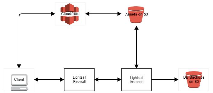
The old setup. A small Lightsail instance with a couple of basic firewall rules. To save instance disk space and hopefully speed up loading time, website assets are stored in an S3 bucket with CloudFront distributing them to website visitors. For those entirely new to AWS, S3 is a basic file storage service and CloudFront is a content delivery network (CDN). The CDN has multiple locations worldwide and caches files from the S3 bucket when website visitors request them. There is a much longer explanation for how CloudFront works, possibly too lengthy to go into here. Maybe in a future post.

My little, cheap as chips Lightsail instance was humming away nicely until it wasn’t. A spike in visitors to one of the sites hosted on it caused a little meltdown. It did recover of course, without any intervention I’ll boastfully add, but it got me thinking about the people that are getting off the ground with their apps, wondering how they’ll move beyond that first little server that can’t really hack it anymore. Potentially even worse than that, startups without any IT people or developers that know a bit of AWS stuff might not actually know about any problems until one of their customers or potential customers calls to report the website or app is down.

I’m not “Scaling for your first ten million users” here, I just want to ride out the peaks and ensure that if something does go down, it wasn’t a server resource capacity issue.

But I’m not going to talk about any of that hypothetical stuff, I want to take a bit of time to show how I moved onto something more future-proof.

In Summary;

What I’m keeping – S3 (Assets & DB backups), CloudFront.

What I’m not keeping – everything else.

Moving away from Lightsail.

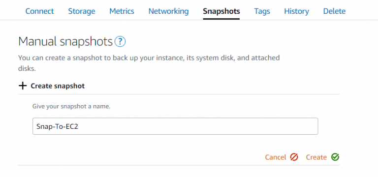
Lightsail, even though it’s a service within AWS, isn’t tightly integrated into the ecosystem. This is where the caveats I mentioned above start to come into play. I initially had the possibly flawed plan of taking my existing instance on Lightsail and just ‘moving’ it to EC2. But it’s not quite so straightforward. What I can do is take a snapshot of the instance and then export that snapshot to EC2.

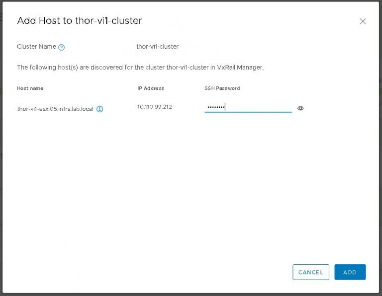
I got the usual warnings/disclaimers about security (I’d need to review firewalling again later) and my Lightsail SSH key would no longer work, so I’d need to create and apply a new one when I launch the image in EC2.

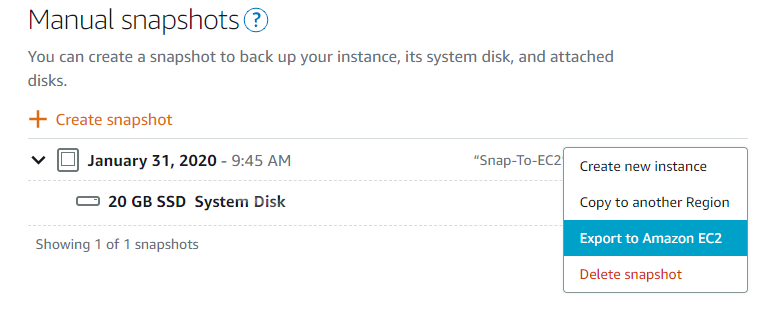
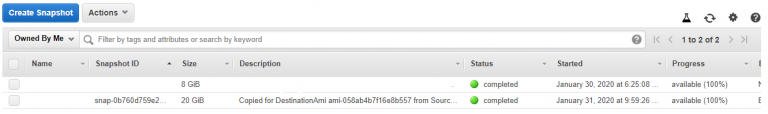
As part of the export to EC2, an AMI (machine image) is also created. Once the export is finished, you can launch an EC2 instance from that AMI. Not overly difficult, just a little time consuming. Also somewhat convoluted if you’re one of those people above that don’t understand a lot of the inner workings of AWS.


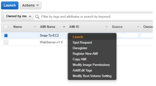
Once the Lightsail export is done, it’s about as simple as right click on the AMI and click launch. I had to do all the normal instance launch stuff like picking an instance type and defining security groups. One important thing to note here is that the Lightsail snapshot is exported to EC2 in the same AWS region as the original Lightsail instance. Neither snapshots nor AMIs have global scope.

Having gone through the above, I then decided that I really didn’t want an exact copy of my existing instance. Changes in the infrastructure were planned that’d make my Lightsail instance obsolete.

Building the new instance

Once I had decided that a brand new instance was needed, I launched a small Ubuntu instance (my distro of choice for the last few years) and set about doing all the normal security hardening and services setup. I installed Nginx, PHP, some PHP extensions and a few more tools I’d need in the future to manage the instance. There is no magic here and there are multiple guides online. To be certain I don’t forget to do something, I usually have one of Digital Ocean’s excellent tutorials open in another window.

Another way I could have done this is to use a standard AWS machine image and employ any one of the configuration management tools; Ansible, Chef, Puppet to do all the configuration and installation for me. But this is just a web server and won’t see huge rate of configuration change. Tooling to manage change is probably overkill right now.

Taking advantage of EFS

I’d read a couple of blog posts on EFS, a relatively new managed file system service from AWS. I wanted to give it a try, but also wanted to be able to step back from it if it didn’t make sense in the long run. I created a new file system across all three availability zones in my chosen region, because ultimately I’ll end up load balancing across all three AZs if the shit hits the fan again. There’s nothing particularly difficult in creating the file system, I pretty much just took default options the whole way through.

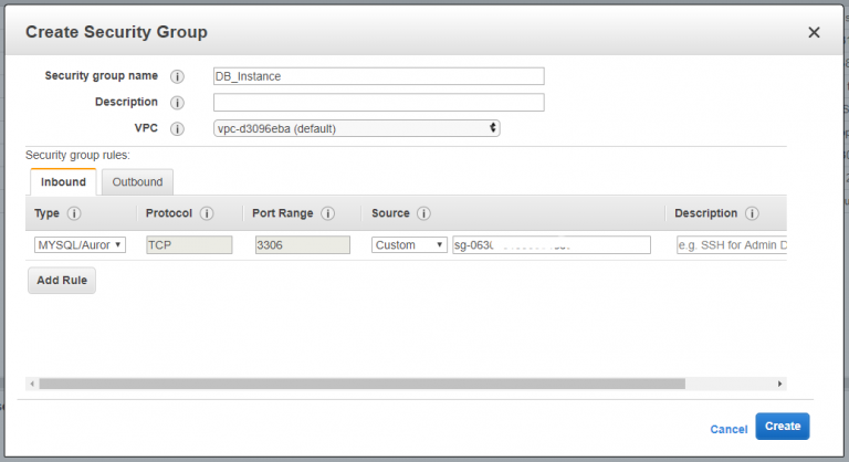
Security group rules caught me out initially, I had forgotten to allow NFS traffic inbound from the security group that the web instances will use. I got a timeout when trying to mount the file system from the Ubuntu instance so the issue was immediately obvious.

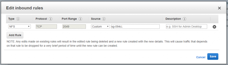
Web instance security group tag partially obfusticated in the above screenshot because of my (crippling) healthy web security paranoia.

On the topic of mounting EFS in the instance, there are a couple of ways to go about it. On Amazon Linux, all the tools are already installed. In Ubuntu, I had to install EFS helper and then just put the mount point into /etc/fstab to have it mount on startup. I did a quick write test to the file system and everything looked good. I’ll give it a little time to see if EFS will work for me and more importantly, how it’ll affect my monthly bill.

As a last act on EFS setup, I cloned the git repo containing my web content to the EFS mount point and configured Nginx to serve from that location.

Auto scaling and load balancing

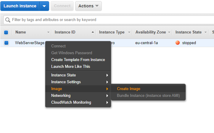
With my Ubuntu instance setup complete, I powered it down and created an AMI.

After this, I created a launch configuration in the EC2 dashboard to use the new AMI and set a few specific options. First, I changed the instance type. I want to try out some of the new(ish) t3a instance types. Second, I disabled public IP address assignment on the instances launched by this configuration. The only access to these instances should be through the load balancer I’ll create later. Lastly, I duplicated the existing security group applied to the staging instance (the one I created the AMI from above) and removed SSH access. I won’t need to log in to the production instances so reducing the potential attack surface a bit.

Next, I created a classic load balancer. Gave it the same security group as above and changed the health check to ping the HTTP port of the web instances and look for a specific URL. When the scaling group I’ll create next scales up, it’ll add the new instance to the load balancer and once HTTP becomes active and the URL I’ve given to it is reachable, the load balancer will start sending traffic to the instance.

I’m not adding instances to the load balancer right now because, well, there aren’t any. When I create the auto scaling group next, I’ll point it at the load balancer and it’ll handle the registration and deregistration of instances.

For the auto scaling group, I decided to try out the new (and improved?) method of first creating a launch template and applying that to an auto scaling group. In theory, I can version launch templates if I decide to change instance type, image or other options so I can swap out instances with less effort. Also, it’s another new thing to play with. Mostly that.

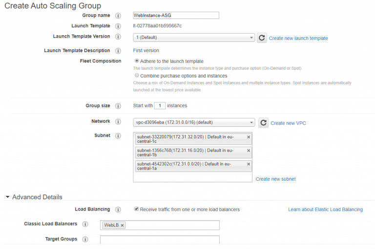
Hopefully the above isn’t too much of an eye chart. I’ve given the ASG a name, picked my launch template version from the list (or choose ‘latest’ which always takes the newest) and defined my VPC and subnets. As I mentioned above, I’ve linked the load balancer to the ASG so all the load balancing wizardry will be taken care of.

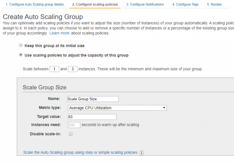
For the scaling policy, I tried to strike a balance between being a cheapskate and having unavailable websites. Usually, scaling at about 40% usage is good for availability. Up to 70% is good for cost. So I picked a number in between.

For notifications, I want to know when a scale out, scale in or instance failure occurs. I created a new SNS topic here and gave it my email address. I might change this out later on to log elsewhere, depending on how spammy it gets.

I finished creating the ASG and it fired up the first instance. Looking at the load balancer, the new instance was out of service and so the load balancer never kicked in. A few minutes of head scratching later, I realised I’d been caught again by my old friend the security group. Extra points if you can guess what I’ve done without rereading the entire post.

No? When I duplicated the security group, I forgot to add an inbound NFS rule on my security group attached to the EFS file system. So instances launched with the new security group couldn’t mount EFS. With that little issue resolved, I relaunched the instances (deleted them, the ASG took care of launching new ones) and hey presto, instance in service.

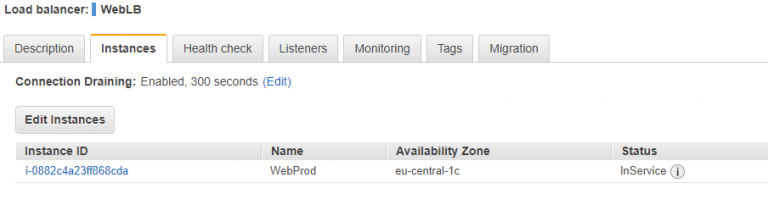
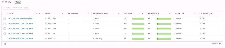
I also verified that instances were launching in separate availability zones by temporarily scaling the group to 3 instances.

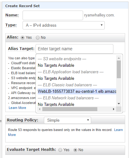
Finally, because WebLB-1855773837.eu-central-1.elb.amazonaws.com doesn’t exactly roll off the tongue to advertise as your website address, I created a record set in Route53 to point to the load balancer.

Database

This part is going to be a little anticlimactic after what I’ve just done above. For the database, I launched a small Ubuntu instance with an IAM role to allow it to interact with an S3 bucket I’m going to use in the next step to send database backups to. For those unfamiliar with IAM, its basically access & permissions management. Like the web instance, the DB instance is internal only. It does not have a public IP address.

I configured all the basics, installed and configured MySQL, then did some security hardening. Nothing too taxing. I also applied a new security group to the instance that only permits MySQL traffic to and from the web instance(s).

I could have gone crazy here and gone with Amazon’s RDS to host the MySQL databases. That’d give me all kinds of backup, availability and scalability options out of the box. Nice option to have, but complete overkill for me. It’d also be a hell of a lot more expensive that running a small Ubuntu instance. In the future, if I find I’m getting bottlenecks on the database instance or the MySQL service is complaining about resources, I’ll just take a short period of downtime, shut down and snapshot the instance, then launch a larger instance from that snapshot.

Backup and monitoring

My requirements here are easily satisfied. My databases are backed up by a very simple bash script I wrote to regularly dump the databases to files, then move those files to an encrypted S3 bucket. The S3 bucket is lifecycled so only the last 10 backups are kept. My rate of change is low, so I might even change that to store fewer files. The files are tiny, so it’s not really costing me anything to store them.

The web assets are also on an S3 bucket, being stored in the standard storage tier. That has something crazy like seven 9’s of availability/durability so I’m not overly worried about anything disappearing. Even if I mistakenly delete something, I can easily upload it again from my PC/laptop/phone/ipad. I could enable versioning on the bucket if I was super paranoid.

The web code is stored in a private repo on Github. I briefly thought about moving it to CodeCommit on AWS but came to the conclusion that it was more trouble than it’s worth.

Monitoring is also pretty relaxed. With the new auto scaling group, I’m notified when a scale up/down occurs or if an instance has failed to launch or terminate. That’s useful because I know immediately if I’m getting a spike in traffic or if something has gone horribly wrong. I’m also notified every time a database backup finishes successfully. All of this is using the Simple Notification Service (SNS) and reports are sent to my email address.

I take a look at CloudWatch every now and then if I want to see a bit more about what’s going on with the instances or if I want to keep an eye on my S3 usage. I’m not currently overly fascinated with creating custom metrics or turning on enhanced monitoring. As before, that’d be overkill. I may create an alarm within CloudWatch to monitor if the healthy instance number in the load balancer goes to zero and report it to an SNS topic. That way I’d know if all instances are down and/or if they just stop serving traffic for some reason.

Wrap up

I chose to set everything up manually for a few reasons. Chief among those is my love of knowing how everything is put together in case/when I need to replace or upgrade a bit of it. I realise I could have clicked a couple of buttons, saved myself some time and just got this all going on Elastic Beanstalk. I love EB for ease of setup. For working with several environments. For dev, staging and production. Blue/Green deployments. CI/CD. All that stuff. I know all the buzzwords. That being said, if I needed repeatable environments I think I’d just go the infrastructure as code route and use CloudFormation or Terraform to manage the environments outside of anything that could be potentially restrictive, like Elastic Beanstalk.

I could have also containerised the web instance and run it on EKS. I could have run it on ECS. As with many things, there are many ways to achieve the same goal. I’d like to think I took something simple that was approaching it’s limits and scaled it without transforming it or complicating it too much. I also added a dev/staging server that I can power on and work on the code without interrupting production. Additionally, it’s all properly version controlled now. It’s also possibly a bit more secure.

It’s now possible for me to do OS patching and upgrading without taking the site down. I can introduce a new custom built AMI into the mix and do a rolling redeploy of the web instances without downtime. I can probably do a lot more, I just haven’t really thought about it yet.

VxRack SDDC to VCF on VxRail; Part 4. Expanding Workload Domains

Quick Links
Part 1: Building the VCF on VxRail management cluster
Part 2: Virtual Infrastructure Workload Domain creation
Part 3: Deploy, Configure and Test VMware HCX
Part 4: Expanding Workload Domains

At the end of part 3, I said

With HCX installed and running, I can move onward. Out of the frying pan and into the fire. Getting some of those production VMs moving.

Except we won’t be doing that, because in a lab scenario, it’d be boring. There isn’t really any interdependency between VMs in my lab. There are no multi-tiered apps running, no network micro-segmentation or any one of the other countless gotchas you have to plan around for a production environment. I’d end up writing a long, detailed post about moving some test VMs between VxRack and VxRail clusters. I’d be rehashing a lot of what I wrote in the previous post regarding VMware HCX migration types and varied migration strategies.

So instead, straight onto expanding workload domains.

After using HCX to migrate some of the initial workload to the VCF on VxRail VI workload domain, the three node cluster is naturally going to get a little resource constrained. At the same time, resources are going to be freed up on the VxRack SDDC nodes. So using the process I detailed in part 1 to build the management and VI workload domain clusters, I’ll convert some more VxRack SDDC nodes into VxRail nodes and expand my VI workload domain.

To briefly recap the conversion process;

  1. Decommission the VxRack SDDC node in SDDC manager.
  2. Power the node down and install hardware (if necessary).
  3. Complete all required firmware updates.
  4. Mount VxRail RASR ISO image and factory reset the node.

With the above completed, I’ve got a brand new VxRail node ready to go. Within vCenter, right click on the cluster name and from the VxRail menu, select Add VxRail Hosts. It may take a few seconds for the new node details to populate. Once the node(s) appear in the list, I can continue by clicking the Add button.

In this case, I’m only going to add one of the four discovered nodes to the cluster.

Provide credentials of an administrative user.

Then verify that a sufficient number of IP addresses in the management, vMotion and vSAN IP pools are free. If not, create additional pools.

Provide more credentials

Finally confirm if the new node(s) will remain in maintenance mode once addition is complete.

Everything looks good, click validate. Once the validation process finishes successfully, I can proceed with the node addition.

Within a few minutes, the new node will be added to the cluster in vCenter. The only problem now is that SDDC manager knows nothing about it. So I’ll fix that. A moderate amount of digging through menus is required. Within SDDC manager, select Inventory > Workload Domains. I picked the workload domain I want to add the node to, in this case ‘thor-vi1-cluster’. Click the Clusters tab to display the VxRail clusters within this workload domain. I don’t believe I’ve covered it yet, but yes, a single workload domain can contain one or more VxRail clusters. Click the cluster to which the node will be added. As you can see in the screenshot below, the actions menu contains a link to add the new node.

All going well (and assuming my new node is setup correctly), it’ll appear in the next dialog (below) after a brief period of discovery.

It did, so no loudmouth troubleshooting is required. Incidentally, as all my top of rack multicast configuration has been carried out on a specific VLAN, I need to do a little modification to new nodes so they’ll see and contribute to the multicast group properly. Otherwise, VxRail manager isn’t going to discover anything. This is slightly different in VxRail 4.7 code, which introduces two new portgroups. Long story short, when I’m bringing up a new node, I change the VLAN assignment for “Private Management Network” to my custom VLAN. The CLI commands are basic, but I’ll include them below for the sake of completeness.

“esxcli network vswitch standard portgroup list” – to check the VLAN assignments for the portgroups.

“esxcli network vswitch standard portgroup set -p “Private Management Network” -v [VLAN]” – to set the VLAN on which multicast is running.

In the spirit of not over complicating it, I always use the ESXi management VLAN as my private management network VLAN. But if you wanted to segregate multicast traffic to its own VLAN, the option is there.

Nothing terribly exciting happens after the above dialog I’m afraid. All there is left to do is watch the status pane in SDDC manager as the new node switches from activating to active. After that happens, the new node is ready to go.

The above is an example of converting and adding a single new node into an existing VxRail cluster & SDDC workload domain. It’s not difficult to imagine that if you were to convert nodes one by one on a large VxRack SDDC system, it would be a job for life. When the migration from VxRack to VxRail is in progress, it makes sense to include as many nodes as possible in each iteration of convert & expand. I can convert several concurrently as easily as converting one, with little additional time penalty. When the time comes to add those converted nodes into a VxRail cluster, it can be a bulk operation.

Needless to say, it should be extensively planned, depending on factors in your environment. If I migrate X amount of VM load from VxRack SDDC cluster Y, then in turn I can remove X number of nodes from VxRack SDDC Cluster Y and immediately make that compute & vSAN storage capacity available on VxRail Cluster Y. That, of course, is a gross oversimplification. What I’m really getting at is, if you’ve got the capacity, don’t do it one by one or you’ll go nuts long before you’ve got your several hundred node VxRack SDDC to VCF on VxRail migration completed.

As you might expect, the above is a ‘rinse & repeat’ process until all the production load is migrated successfully from VxRack to VxRail. Either continue to add capacity to existing VxRail clusters/workload domains, or create new additional workload domains using the process covered in part two of this series.

As for the questions I’ve been answering throughout this series;

How long is it going to take? – About four hours to convert a node if you insist on doing it the painful (one by one) way. That is everything from the initial decommission out of VxRack SDDC manager, hardware changes (if required), creating the RASR partition, installing the VxRail code and waiting for the ESXi configuration. Adding nodes to VxRail clusters and VCF workload domains is pretty trivial. Let’s add another 15 minutes or so for that. As above, many nodes at once make lighter work. Lighter still if you automate the process.

How much of it can be automated? – So, so much. Almost the entire conversion process is a candidate for automation. In an ideal scenario, I’d let automation take the reins after I’ve confirmed that the node(s) are successfully decommissioned from VxRack SDDC and I’ve completed any necessary hardware changes. I probably wouldn’t automate the addition of those newly converted nodes to VxRail clusters, but maybe that’s just me.

Next up, I’m going to be doing something short and sweet. I’ll be destroying the VxRack SDDC management workload domain and reclaiming the resources therein.